Eyewear incorporating lenses with electronically variable optical properties

a technology of optical properties and lenses, applied in the field of eyewear, can solve the problems of not allowing the lens to be ground, unable to facilitate the assembly of eyewear with a specific electro-optic lens design, and unable to incorporate an electro-optic device into a prior art eyewear fram

Inactive Publication Date: 2009-10-08
ALPHAMICRON INC
View PDF11 Cites 57 Cited by
  • Summary
  • Abstract
  • Description
  • Claims
  • Application Information

AI Technical Summary

Problems solved by technology

Unfortunately, this approach does not facilitate assembly of eyewear with a specific electro-optic lens design, wherein the electro-optic materials may be selected from liquid crystals, electro-chromics, electro-phoretics and the like.
Such a configuration does not allow the lens to be ground arbitrarily to a shape that will fit into an eyewear frame.
As noted, attempting to incorporate an electro-optic device into a prior art eyewear frame is problematic.
Accordingly, the lens, the edge seal, and / or the electrode tabs are typically not robust enough to survive insertion into an elastically deformed frame.
However, an electro-optic lens, such as a liquid crystal lens, by itself, cannot withstand such forces.
These components must be located somewhere in or on the frame while maintaining an aesthetically pleasing appearance or indeed, be totally unobservable by the wearer or the casual observer.
It is submitted that the known prior art does not address the details of incorporating the lenses, drive circuits, batteries, and interconnections into the frames in an attractive manner.

Method used


Image

  • Eyewear incorporating lenses with electronically variable optical properties
  • Eyewear incorporating lenses with electronically variable optical properties
  • Eyewear incorporating lenses with electronically variable optical properties

Examples


Embodiment Construction

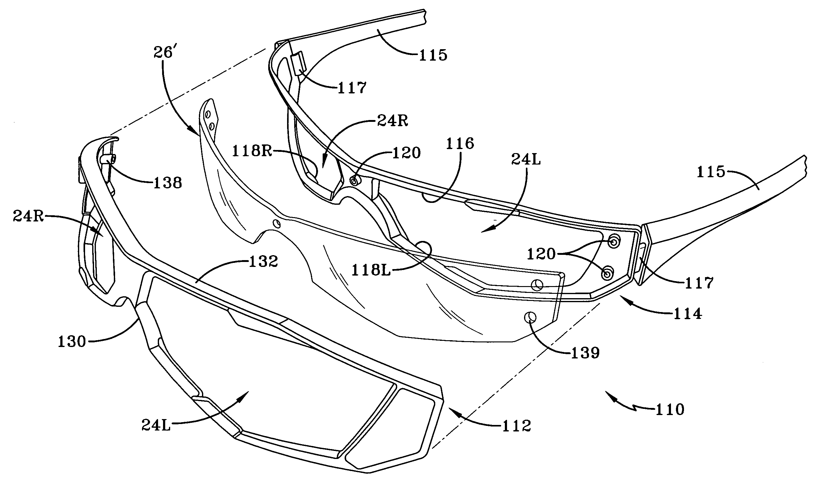
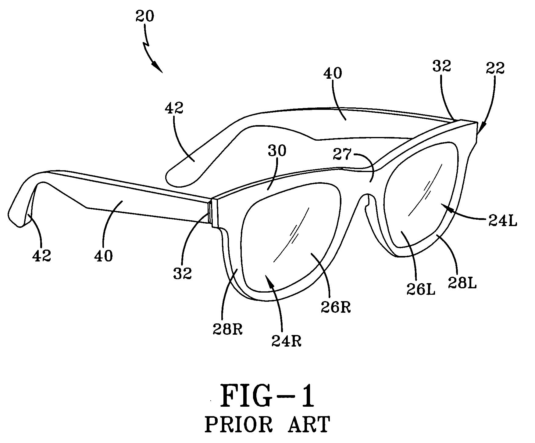
[0043]Referring now to the drawings, and in particular to FIG. 1, it can be seen that a prior art eyewear assembly is designated generally by the numeral 20. It will further be appreciated that the eyewear assembly may also be referred to as glasses, spectacles, or the like. The eyewear assembly includes a frame 22 which provides at least one aperture 24 which carries a lens 26, which may also be referred to as an optical device. In most eyewear, it will be appreciated that two apertures are provided wherein each aperture is associated with the wearer's eye. Accordingly, the apertures, lenses and other related components associated with the wearer's left eye are provided with a capital letter L suffix and the aperture, lens and other components associated with the wearer's right eye are provided with a capital letter R suffix. The frame 22 may include a bridge 27 which separates a rim 28L from a rim 28R. And the frame may be provided in either a rimmed, semi-rimless or rimless confi...


PUM


Abstract

An electro-optic eyewear assembly having a frame with opposed ends, a pair of temples, and a hinge mechanically interconnecting each temple to a corresponding end of the frame. Each temple moveable between a wearing position and a storage position and at least one electro-optic lens carried by the frame and a control circuit carried by at least one of the temples. The electrical connection between the control circuit and the at least one electro-optic lens being made by moving one of the temples into physical contact with the frame when the temple carrying the control circuit is moved to a wearing position.

Description

CROSS-REFERENCE TO RELATED APPLICATIONS[0001]This application claims priority of U.S. Provisional Application Ser. Nos. 60 / 843,599 filed Sep. 11, 2006 and 60 / 919,416 filed Mar. 22, 2007, both of which are incorporated herein by reference.TECHNICAL FIELD[0002]The present invention is generally directed to eyewear. More specifically, the present invention is directed to eyewear with lenses using electronically controllable variable optical properties such as those available with liquid crystal materials.BACKGROUND ART[0003]Eyewear is believed to have been developed in Europe and China during the thirteenth century. It is also believed that primitive man used shields made from bone and / or wood to protect their eyes from sun and wind. Primarily, eyewear was developed for functional reasons, namely to improve the wearer's vision and to protect their eyes from environmental elements. As time passed, eyewear as a fashion accessory became common.[0004]Eyewear has many basic components and g...

Claims


Application Information

Patent Timeline
Patent Type & Authority Applications(United States)
IPC IPC(8): G02C1/00H02J7/00
CPCG02F1/13452G02C7/101
Inventor FIGLER, JONATHANKOSA, TAMASMILLER, ROYMARTINCIC, CHRISTINEPARK, EUI-YEULTAHERI, BAHMAN
Owner ALPHAMICRON INC
Why Eureka
Try Eureka