Fuel Cell System and Its Operation Stop Method

a fuel cell and operation stop technology, applied in the direction of electrochemical generators, operating means/releasing devices of valves, machines/engines, etc., can solve the problems of high-precision pressure adjustment in which a target pressure is changed over multiple stages, the response is low, and the difficulty in quickly changing the supply pressure of a fuel gas, etc., to achieve the effect of improving the reliability of the start in the low temperature environmen

Active Publication Date: 2009-10-08
TOYOTA JIDOSHA KK
View PDF2 Cites 11 Cited by
  • Summary
  • Abstract
  • Description
  • Claims
  • Application Information

AI Technical Summary

Benefits of technology

[0033]According to the present invention, since the water present around the valve body of the injector can be reduced when the system stops, an operation defect due to the freezing in the injector can be inhibited, and start reliability in the low temperature environment can be improved.

Problems solved by technology

However, it has been difficult to quickly change a supply pressure of a fuel gas (i.e., response is low) owing to a structure of the conventional mechanical variable pressure adjustment valve described in JP2004-139984A mentioned above, and further, high-precision pressure adjustment in which a target pressure is changed over multiple stages have not been able to be performed.
Moreover, since the conventional mechanical variable pressure adjustment valve has a comparatively complicated constitution, the valve has a large size and a large weight, so costs of manufacturing increase.
Therefore, problems of enlargement of the system (enlargement of an installation space) and increase of equipment costs are caused.
Therefore, if the water remaining at the pressure adjustment valve freezes, a stable operation of the pressure adjustment valve on low-temperature start-up is disturbed.

Method used


Image

  • Fuel Cell System and Its Operation Stop Method
  • Fuel Cell System and Its Operation Stop Method
  • Fuel Cell System and Its Operation Stop Method

Examples


Embodiment Construction

[0041]A fuel cell system 1 according to an embodiment of the present invention will hereinafter be described with reference to the drawings. In the present embodiment, an example will be described in which the present invention is applied to a car mounted power generation system of a fuel cell vehicle (a mobile body).

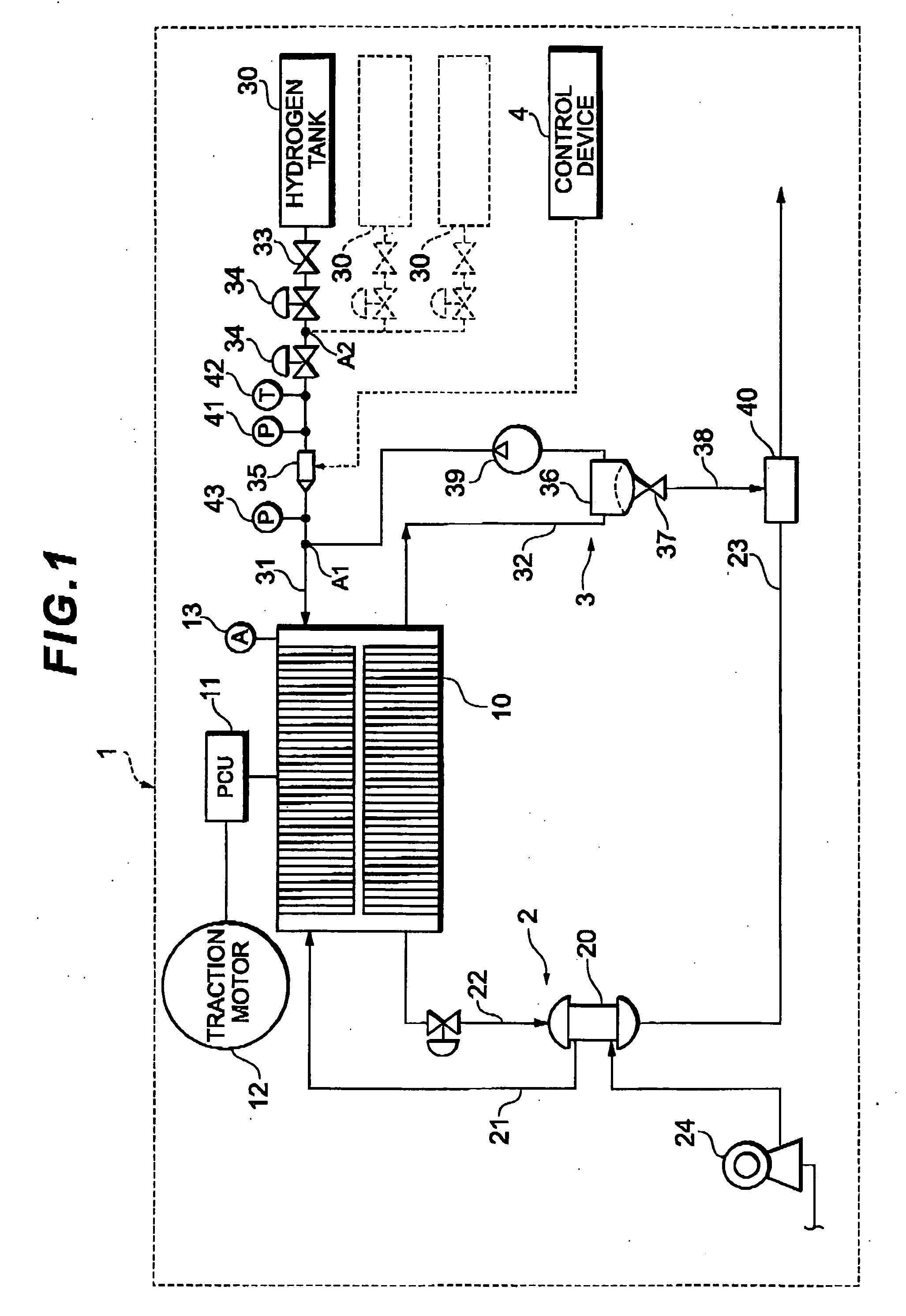
[0042]First, a constitution of the fuel cell system 1 according to the embodiment of the present invention will be described with reference to FIG. 1.

[0043]As shown in FIG. 1, the fuel cell system 1 according to the present embodiment includes a fuel cell 10 which receives supply of a reactant gas (an oxidizing gas and a fuel gas) to generate power, an oxidizing gas pipe system 2 which supplies air as the oxidizing gas to the fuel cell 10, a hydrogen gas pipe system 3 which supplies a hydrogen gas as the fuel gas to the fuel cell 10, a control device 4 which generally controls the whole system and the like.

[0044]The fuel cell 10 has a stack structure constituted by lami...


PUM

PropertyMeasurementUnit
pressureaaaaaaaaaa
temperatureaaaaaaaaaa
pressureaaaaaaaaaa

Abstract

The present invention provides a fuel cell system including a fuel cell, a hydrogen gas pipe system for supplying a fuel gas to the fuel cell, and an injector for adjusting a pressure of the upstream side of the hydrogen gas pipe system to supply the hydrogen gas to the downstream side, wherein the injector includes an internal channel for communicating the upstream side of the injector with the downstream side of the injector, and a valve body movably arranged in the internal channel for switching a channel opening area in multiple stages corresponding to a movement position of the valve body, and wherein water at least around the valve body of the injector is reduced when the system stops.

Description

TECHNICAL FIELD[0001]The present invention relates to a fuel cell system in which a gas supply system of a fuel cell is provided with an injector, and an operation stop method of the system.BACKGROUND ART[0002]At present, a fuel cell system including a fuel cell that receives supply of a reactant gas (a fuel gas and an oxidizing gas) to generate power has been proposed and put to practical use. Such a fuel cell system is provided with a fuel supply channel for introducing the fuel gas to be supplied from a fuel supply source such as a hydrogen tank into the fuel cell.[0003]Meanwhile, a pressure adjustment valve (a regulator) which reduces a supply pressure to a certain value is generally disposed along a fuel supply channel, when the supply pressure of the fuel gas from the fuel supply source is remarkably high. In recent years, a technology is proposed in which a mechanical variable pressure adjustment valve (a variable regulator) for changing the supply pressure of the fuel gas in...

Claims


Application Information

Patent Timeline
Patent Type & Authority Applications(United States)
IPC IPC(8): H01M8/04
CPCF02D33/006Y02E60/50H01M8/04201F16K31/0655
Inventor KATANO, KOJIYAMAGISHI, NORIOHOTTA, AKIHISA
Owner TOYOTA JIDOSHA KK
Why Eureka
Try Eureka