Dual Mode Radio Frequency Front End Circuit

Inactive Publication Date: 2009-10-08
STMICROELECTRONICS SRL
View PDF6 Cites 35 Cited by
  • Summary
  • Abstract
  • Description
  • Claims
  • Application Information

AI Technical Summary

Benefits of technology

[0013]The amplifier operates as a power amplifier when its input port is electrically connected to the first switch due to selective operation of the second switch.

Problems solved by technology

There are several disadvantages associated with existing front end circuits.
The front end circuits require two switches to operate, which increases cost and space requirement inside a module.
The need for two switches also causes increased power loss during a receive mode.
Also, the front e

Method used


Image

  • Dual Mode Radio Frequency Front End Circuit
  • Dual Mode Radio Frequency Front End Circuit
  • Dual Mode Radio Frequency Front End Circuit

Examples


Example

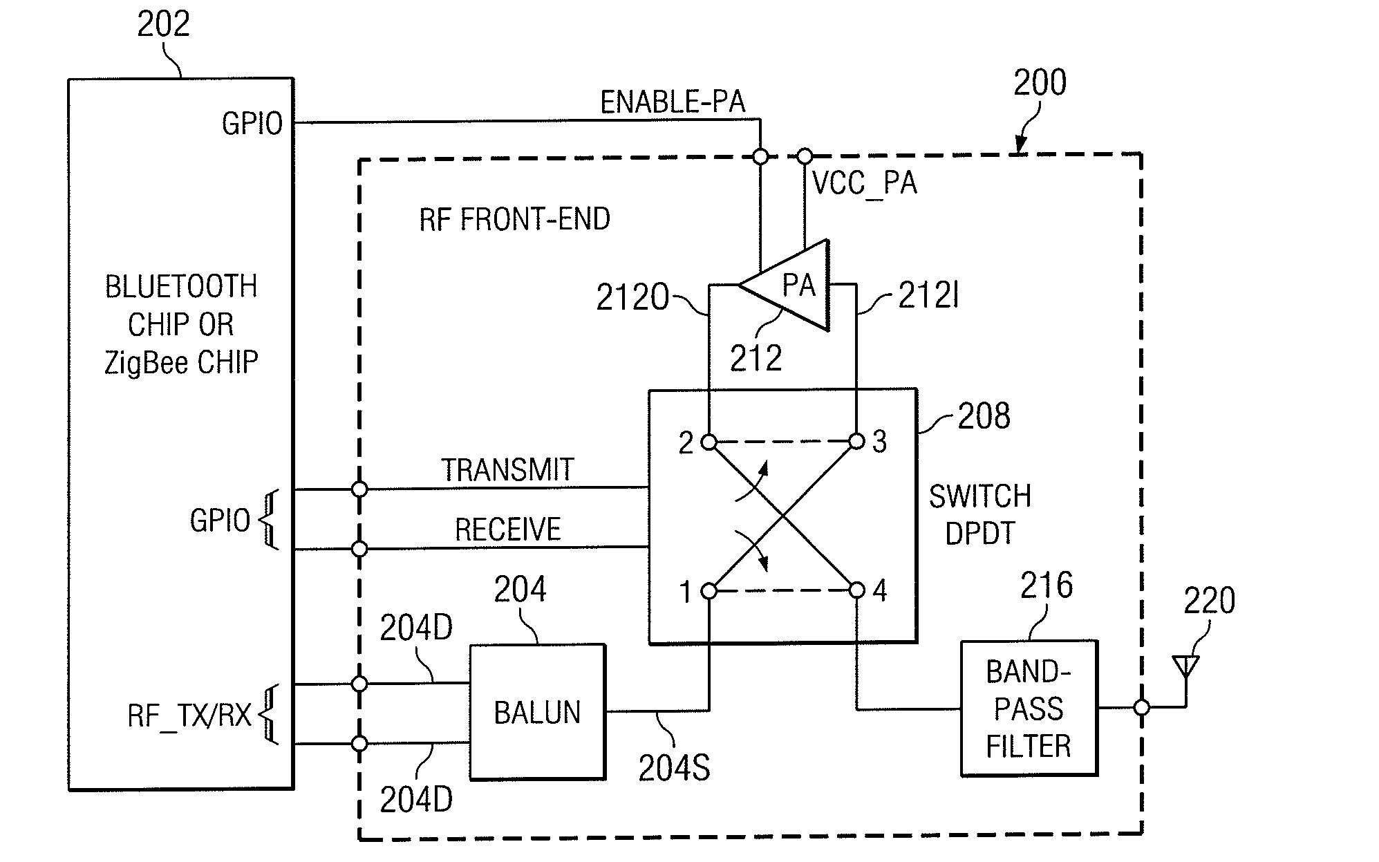
[0024]A radio frequency (RF) front end circuit 200 in accordance with one example embodiment is shown in FIG. 2. The front end circuit 200 may be used in mobile phones, personal computers, and other wireless devices. In particular, the front end circuit 200 may be coupled to an RF transceiver 202 such as a Bluetooth or a ZigBee transceiver used in wireless devices.

[0025]The front end circuit 200 includes a transformer 204 for conversion between balanced and unbalanced RF signals. In particular, the transformer 204 may be a balun with primary and secondary windings configured to provide a differential terminal 204D and a single-ended terminal 204S. The differential terminal 204D of the transformer 204 is coupled to an RF transmit-receive (RF_TX / RX) terminal of the transceiver chip 202.

[0026]During transmission, the transformer 204 receives a balanced RF signal at the differential terminal 204D from the transceiver chip 202 and generates an unbalanced RF signal at the single-ended ter...


PUM


Abstract

A dual mode radio frequency (RF) front end circuit includes a first transformer for conversion between a balanced and an unbalanced RF signal and a second transformer for conversion between a balanced and an unbalanced RF signal. A first switch is configured to selectively electrically connect to one of the first transformer, the second transformer and an RF transmit port. A second switch is configured to selectively electrically connect the first switch and a filter to one of the input and the output port of an amplifier. The first switch is connected to the input port of the amplifier when the filter is connected to the output port of the amplifier, and the first switch is connected to the output port of the amplifier when the filter is connected to the input Port of the amplifier. The first and the second switch cooperatively selectively connect one of the first transformer, the second transformer and the RF transmit port to the amplifier and the filter.

Description

TECHNICAL FIELD[0001]This disclosure relates generally to electronic circuits and, more particularly, this disclosure relates to dual mode radio frequency (RF) front end circuits for wireless devices.BACKGROUND[0002]Radio Frequency (RF) front end circuits are used in wireless devices such as mobile phones, personal digital assistants, lap-top computers and other communication devices. The front end circuits are typically coupled to a transceiver chip (e.g., Bluetooth or ZigBee) in a wireless device. They increase the range of a wireless link by delivering increased output power during transmission along with low-pass filtering of harmonics while band-pass filtering during reception.[0003]The front end circuits are often implemented as integrated modules. FIG. 1A illustrates a conventional RF front end circuit 100, which may be implemented as an integrated module interfacing with a transceiver chip 104 and an antenna 108. The front end circuit 100 includes a transformer 112 (balun) w...

Claims


Application Information

Patent Timeline
IPC IPC(8): H04B1/44H04B1/06
CPCH04B1/44
Inventor GORBACHOV, OLEKSANDR
Owner STMICROELECTRONICS SRL
Why Eureka
Try Eureka