
Clean Transportation System

a transportation system and biological material technology, applied in the field of sterile biological material containers, can solve the problems of contamination, blood sterility may be compromised, and the conventional transportation method and device for biological materials between sterile and non-sterile fields suffer from certain disadvantages, so as to achieve the effect of maintaining sterility of biological material containers

Active Publication Date: 2009-10-08
BIOMET MFG CORP
View PDF4 Cites 68 Cited by
  • Summary
  • Abstract
  • Description
  • Claims
  • Application Information

AI Technical Summary

Benefits of technology

The patent describes a transportation system for safely transporting biological material containers between sterile and nonsterile fields while maintaining their sterility. The system includes a housing assembly with a port for accessing the container, and a first and second member that cover different parts of the container. The first member covers the first part of the container, while the second member covers the second part. The second member is removably attached to the first member to allow for easy removal of the container. The system also includes a keying member that ensures the housing assembly is positioned correctly in a centrifuge. The technical effects of this system include improved safety and protection of biological materials during transportation and centrifugation.

Problems solved by technology

However, conventional methods and devices for transporting biological materials between sterile and nonsterile fields suffer from certain disadvantages.
For instance, in the example discussed above, the sterility of the blood may be compromised, especially when the blood is introduced to the cups.
More specifically, although the cups are located in the sterile field, the cups are still somewhat exposed to the environment inside the operating room, and contamination may occur.
Furthermore, these conventional methods and devices can be time consuming and inconvenient because the fluids are transferred between a substantial number of vessels.
In addition, a substantial amount of waste can be produced using these methods because once a vessel is used, it is typically discarded.

Method used


Image

  • Clean Transportation System
  • Clean Transportation System
  • Clean Transportation System

Examples


Embodiment Construction

[0021]The following description of the embodiment(s) is merely exemplary in nature and is in no way intended to limit the invention, its application, or uses. Moreover, the container system described herein is discussed in association with a biological material container of a type shown in U.S. Pat. No. 7,179,391, which issued Feb. 20, 2007, U.S. Patent Publication No. 2005 / 0109716, which was filed on Sep. 2, 2004, and / or U.S. Patent Publication No. 2006 / 0278588, which was filed on May 26, 2006, each of which are incorporated herein by reference. However, it will be appreciated that the container system can be used in association with any suitable biological material container without departing from the scope of the present disclosure.

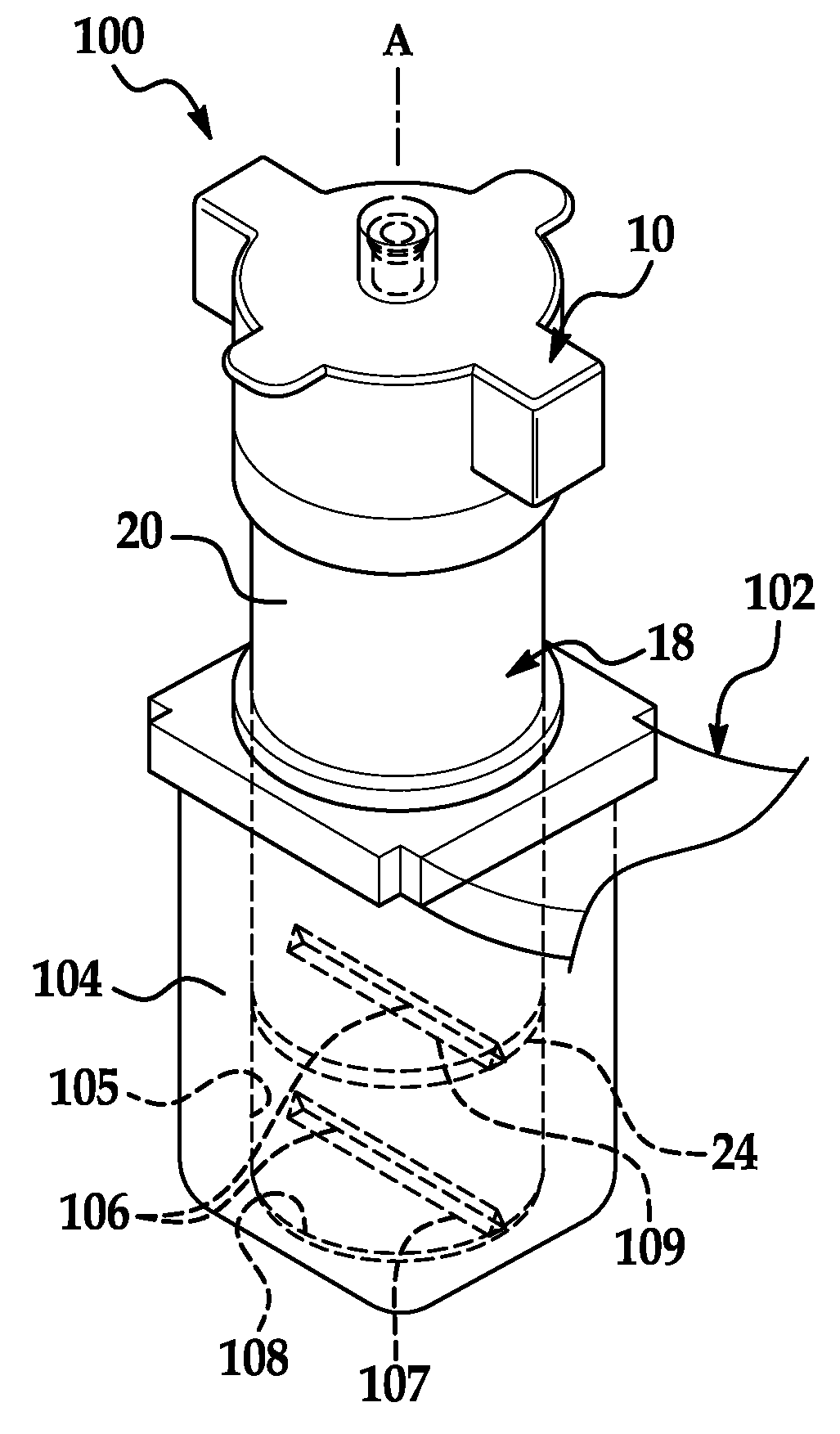
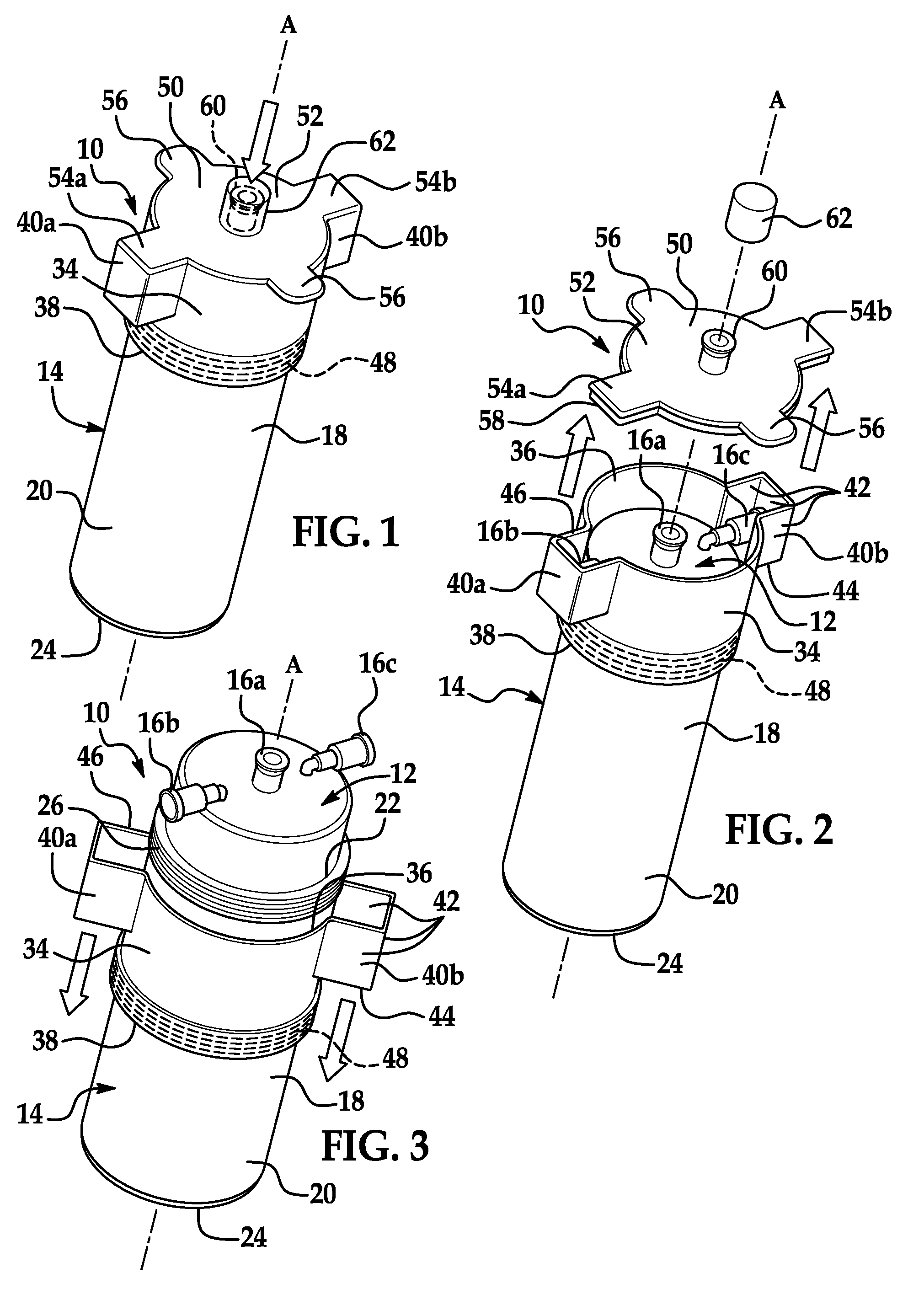
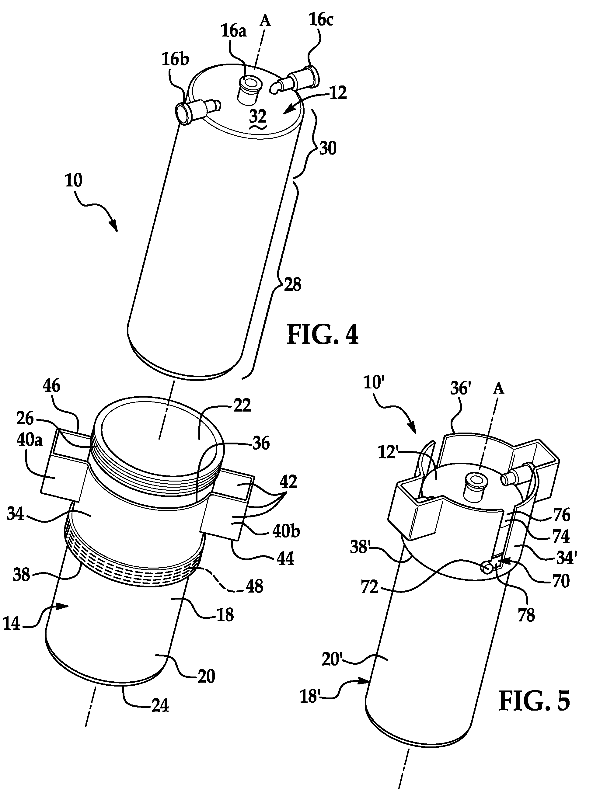
[0022]With initial reference now to FIGS. 1-4, a biological material container system 10 is illustrated. The system 10 generally includes a biological material container 12 and a transportation system 14. The biological material container 12 is removab...


PUM


Abstract

A transportation system for transporting a biological material container between a sterile field and a nonsterile field and substantially maintaining sterility of the biological material container includes a housing assembly that removably houses the biological material container. The system also includes a port defined by the housing assembly, and the port provides communication into the biological material container from outside the housing assembly. The housing assembly includes a first member that covers a first portion of the biological material container such that a second portion of the biological material container extends from the first member. The housing assembly also includes a second member that covers the second portion of the biological material container. The second member is removably coupled to the first member to expose the second portion of the biological material container. A keying member that keys the transportation system in a centrifuge is also disclosed.

Description

FIELD[0001]This invention relates to a sterile biological material container, and more particularly, to a clean transportation system for a sterile container.INTRODUCTION[0002]Certain methods and devices have been proposed for maintaining sterility of biological materials when being transported between sterile and nonsterile fields. For instance, in some cases, blood is obtained in a sterile field from a patient and is introduced into a sterile vessel where it is protected from contamination. Then, the vessel is transferred to a nonsterile field and is spun in a centrifuge to separate the components of the blood. Next, a syringe is used to aspirate one or more blood components from the vessel. Subsequently, the blood is aspirated from the syringe into one or more sterile cups located inside the sterile field, and one or more of the separated components is then used depending on the surgical procedure.[0003]However, conventional methods and devices for transporting biological materia...

Claims


Application Information

Patent Timeline
Patent Type & Authority Applications(United States)
IPC IPC(8): B04B5/00B65G1/02
CPCB01L3/5021B01L3/508B01L9/06B01L2200/025B01L2200/141Y10T436/25375B01L2300/0832B01L2400/0409B65B69/00Y10T436/2525B01L2300/041
Inventor CHAVARRIA, JASON
Owner BIOMET MFG CORP
Learn More