Vehicle

a technology for vehicles and vehicles, applied in the field of vehicles, can solve the problems of lateral overturning of vehicles, insufficient stability, waste of energy, etc., and achieve the effects of increasing the vertical load of the inner wheel during cornering, increasing the cornering force, and increasing the vehicle weigh

Active Publication Date: 2009-10-15
EQUOS RES
View PDF15 Cites 15 Cited by
  • Summary
  • Abstract
  • Description
  • Claims
  • Application Information

AI Technical Summary

Benefits of technology

[0023]According to the vehicle set forth in claim 1, by connecting a pair of wheels with a link mechanism and by bending and stretching the link mechanism with a driving force of a link driving device, the pair of wheels can be inclined in the same direction as each other. In other words, during cornering, because the pair of wheels can be inclined together toward inside of cornering to generate a camber thrust by a lateral force, there is an effect that an increase in cornering force can be attempted.
[0024]In addition, according to the vehicle of the present invention, during cornering, at the same time as inclining the pair of wheels, an occupant portion can be inclined in the same direction as the direction of such an inclination of the pair of wheels (that is, the pair of wheels inclined toward inside of cornering). Hereby, because the position of center of gravity of the vehicle can be moved toward an inner wheel during cornering (that is, the position of center of gravity of the vehicle can be moved toward above the inner wheel during cornering), there is an effect that more vehicle weight by that much can act on the inner wheel during cornering, thus increasing a vertical load of the inner wheel during cornering.
[0025]As a result, because a counteracting force against a centrifugal force can be increased, there are effects that lifting of the inner wheel during cornering can be prevented, and also that the ratio of vertical load between outer and inner wheels during cornering can be equalized to improve cornering performance.
[0026]In addition, if the occupant por

Problems solved by technology

As a result, there has been a problem of wasting energy because, for example, a four-seated vehicle is driven, loaded only with the driver.
However, there has been a problem in such vehicles (two-wheeled vehicles for one person) that, when a lateral acceleration (centrifugal force, indicated by

Method used


Image

  • Vehicle
  • Vehicle
  • Vehicle

Examples


first embodiment

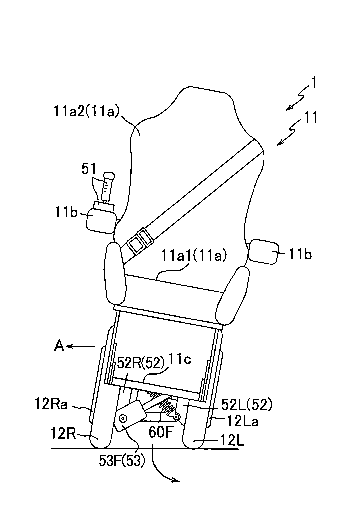
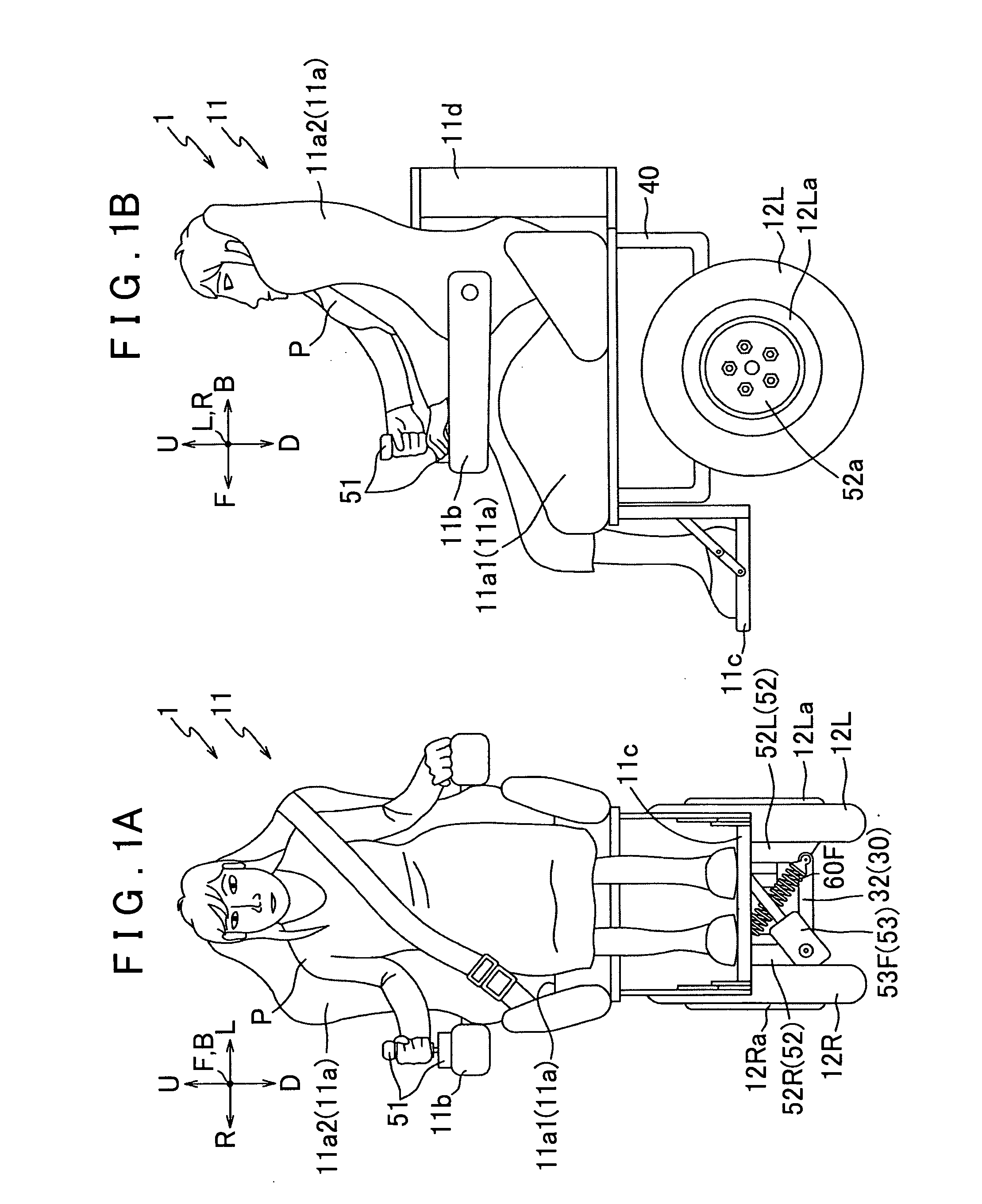
[0100]Preferred embodiments of the present invention will be described below with reference to the accompanying drawings. FIG. 1A is a front view of a vehicle 1 according to the present invention, and FIG. 1B is a side view of the vehicle 1. Note that FIG. 1 shows a state in which an occupant P is sitting on a seat 11a. In addition, arrows U-D, L-R, and F-B in FIG. 1 indicate a vertical direction, a lateral direction, and a longitudinal direction, respectively, of the vehicle 1.

[0101]First, an outline structure of the vehicle 1 will be described. As shown in FIG. 1, the vehicle 1 mainly includes an occupant portion 11 in which the occupant P rides, (a pair of) left and right wheels 12L and 12R that are provided below the occupant portion 11 (at the bottom of FIG. 1), and a rotational drive unit 52 that applies rotational driving forces to the left and right wheels 12L and 12R (refer to FIG. 6), and the vehicle 1 is structured such that, by giving camber angles to the left and right ...

second embodiment

[0185]As shown in FIG. 11, in the link mechanism 130 of the second embodiment, the center distance between the supporting shafts 80Fa and 80Fb via which the R and L motors 152R and 152L support the both ends of the upper link 131 is a distance of smaller dimension than the center distance between the supporting shafts 80Fc and 80Fd via which the R and L motors 152R and 152L support the both ends of the lower link 32.

[0186]Hereby, when the link mechanism 130 is bent and stretched by a driving force of the F actuator 53F, etc., the total value of the camber thrust generated on the left and the right wheels 12L and 12R can be increased while keeping the same inclination angle θC of the occupant portion P, compared with the case in which the above-described center distances do not differ from each other (that is, the link mechanism 30 as a parallelogram link mechanism in the first embodiment, refer to FIG. 8).

[0187]For example, in the case that the link mechanism 130 of the second embod...

third embodiment

[0194]As shown in FIG. 12, in the link mechanism 330 of the third embodiment, both ends of an upper link 331 are rotatably supported via shafts by upper shaft-supporting plates 352b of an R motor 352R and an L motor (not shown), and in the same way, both ends of a lower link 332 are rotatably supported via shafts by lower shaft-supporting plates 352c (the other not shown) of the R motor 352R and the L motor (not shown), respectively; thus, with the upper and lower links 331, 332 and the R and L motors 352R (the other not shown), the four bar link mechanism 330 is structured as a parallelogram link mechanism.

[0195]Here, the R motor 352R of the third embodiment will be described with reference to FIG. 13. FIG. 13A is a front view of the R motor 352R, and FIG. 13B is a side view of the R motor 352R. Note that, in the same way as in the case of the first embodiment, in the third embodiment also, a description about the L motor is omitted, because the L motor and the R motor 352R are str...


PUM


Abstract

By bending and stretching a link mechanism, both left and right wheels of a vehicle can be inclined toward inside of cornering to generate a camber thrust as a lateral force, i.e. an increase in cornering force. Further, by bending and stretching the link mechanism, the passenger compartment can be inclined in accordance with inclination of a connecting link, and thus the center of gravity of the vehicle can be moved toward its inner wheel during cornering. By preventing lifting of the inner wheel during cornering, cornering performance is improved. Because the passenger compartment is inclined toward the inner wheel during cornering, centrifugal force is less likely to be felt by the occupant.

Description

TECHNICAL FIELD[0001]The present invention relates to a vehicle having a pair of wheels and a link mechanism for supporting the pair of wheels, and more particularly to a vehicle that can improve its cornering performance to perform a stable cornering and also that can reduce burden on an occupant to ensure comfort.BACKGROUND ART[0002]In recent years, in view of problems of exhaustion of energy resources, saving in vehicle fuel consumption has been strongly demanded. On the other hand, due to reduction in vehicle prices and so on, vehicle owners have increased to such an extent that there is a trend that each person owns one vehicle. As a result, there has been a problem of wasting energy because, for example, a four-seated vehicle is driven, loaded only with the driver.[0003]Consequently, various studies are being made to downsize vehicles for saving fuel consumption. As a method for saving fuel consumption by downsizing a vehicle, it can be said that the vehicle is the most effici...

Claims


Application Information

Patent Timeline
IPC IPC(8): B60G21/05
CPCB60G21/007B60G2300/122B60G2300/45B62D61/00B62K5/10B62K17/00B62K11/007
Inventor HORIGUCHI, MUNEHISAHASEBE, MASAHIROMIKI, NOBUAKITACHIBANA, TAKUMINAITO, TAKASHIDOI, KATSUNORIHOSOKAWA, TSUKASA
Owner EQUOS RES
Why Eureka
Try Eureka