Apparatus and method for ground fault detection and location in electrical systems

a technology for electrical systems and apparatuses, applied in short-circuit testing, emergency protective arrangements for limiting excess voltage/current, instruments, etc., can solve problems such as circuit board failure, unintentional grounding, and major failures of electric equipment, and achieve rapid and efficient repair and recovery practices.

Inactive Publication Date: 2009-10-15
WEEMS II WARREN A +2
View PDF4 Cites 28 Cited by
  • Summary
  • Abstract
  • Description
  • Claims
  • Application Information

AI Technical Summary

Benefits of technology

[0018]The ground fault detection and location apparatus is capable of operating in six different modes, with each mode providing a different capability or opportunity for detecting, analyzing, and locating one or more unintentionally grounded circuits in an normally ungrounded AC or DC power distribution system. In the first mode, the ground fault detection and location apparatus is in the de-energized state and the ground fault detection and location apparatus is non-operational. In the second mode, data about the system voltage being monitored by the ground fault detection and location apparatus is displayed on a screen and the information may be used for analyzing a specific situation. In the third and forth modes, the ground fault detection and location apparatus can be used to detect ground faults and provide additional data to help the user of the ground fault detection and location apparatus gain additional insight into the operational characteristics of the electrical system being monitored by ground fault detection and location apparatus. By switching to a fifth and / or sixth mode, the ground fault detection and location apparatus of the present invention can be used to locate ground faults in a rapid and efficient fashion.
[0019]The most preferred embodiments of the present invention employ methods of detecting and locating one or more unintentionally grounded circuits in a normally ungrounded AC or DC power distribution system using the main unit to detect and analyze ground faults and using the secondary unit” for sensing current manipulations introduced onto the circuit by main unit. The main unit displays various voltage, current, and phase angle measurements related to the flow of electricity in the circuit. Additionally, the main unit is configured to manipulate the ground fault current at two specific frequencies. Using the ground fault location sensing unit, a technician will then search for the manipulated ground fault current on individual branch circuits until the manipulated current is discovered on the faulted branch circuit by deploying one or more secondary sensing units. The secondary unit also acts as an analyzing tool and therefore by analyzing the branch circuit-level response to the ground fault current manipulation, the specific location of the ground fault or faults can be more readily ascertained, thereby promoting rapid and efficient repair and recovery practices. The components and circuits of the apparatus of the present invention may be also be implemented as a dedicated, permanent ground fault detector device installation. It is anticipated that the various preferred embodiments of the present invention will find application in a wide variety of industries and locations including maritime and naval operations, mining operations, large manufacturing operations such as paper mills, hospitals, transmission substations and power plants, etc.

Problems solved by technology

A “ground fault” is an undesirable condition in an electrical distribution system, where the electrical current in the system flows or “leaks” outside of its intended flow path.
Electrical faults in most ungrounded electrical distribution systems will typically not shut the system down but will, instead, result in the generation of an alarm, thereby providing an alert while maintaining any critical loads in an energized condition.
Undesirable and unintended ground faults on ungrounded electrical distribution systems can result from many several different situations.
For example, some major failures in electric equipment are caused by insulation breakdowns.
Over time, the insulation on the electrical cables or wires can degrade, thereby exposing the conductors to other conducting materials, resulting in an unintentional grounding.
Other types of failures that may introduce ground faults include circuit board failures, excess moisture being introduced into the electrical distribution system, bad wire joints and sleeves, leaking batteries, accidental grounds caused during testing, component failure, etc.
Even more important and generally far more difficult than ground fault detection is the problem of ground fault location.
While a ground fault detection system may accurately reveal that a ground fault exists on a given ungrounded electrical distribution system, the task of pinpointing the exact location of the ground fault is typically far more difficult to accomplish.
Failure to quickly locate and rectify a ground fault may lead to equipment failure, inadvertent exposure to dangerous electrical environments, and other undesirable outcomes including reduction or termination of production or, in extreme cases, plant outages.
While it is important to locate ground faults as quickly and efficiently as possible, certain practical realities can complicate this task.
For example, many circuits suffer from frequency induced “noise.” In these circuits, if a ground fault current at a normally detectable current level is present but yet lower in magnitude than the background noise on the electrical distribution system, traditional ground fault location equipment may not be able to distinguish between the actual ground fault and the ambient noise on the circuit.
The result will be an inability to locate the circuit containing the ground fault.
Accordingly, many traditional ground fault locating devices are be incapable of locating high resistance ground faults due to either a low amount of ground fault current, excessive noise on the system, or a combination of both.
These long distribution runs, being capacitive in nature, can impede current flow in certain circuits, effectively creating the appearance of a ground fault where there is none.
This can make the location of the actual ground fault far more difficult in some electrical distribution systems.
In other circumstances, intermittent, cycling or momentary ground faults or multiple ground faults on an ungrounded electrical distribution system may occur.
During the time that the technician is investigating the ground fault, the strength of the ground fault may change or the ground may become intermittent, cycling or momentary stopping altogether, consequently making the entire location effort difficult if not futile.
Similarly, other ground faults may be hidden in control circuit operations and may occur only during the transitory operation of a single switch.
This approach is very time consuming and leads to a great deal of “trial and error” searching, hoping to stumble across the appropriate branch circuit where the ground fault is located.
Thus, while certain techniques are available for detecting and locating ground faults in normally ungrounded electrical distribution systems, present systems and methods are sub-optimal due to the inherent limitations in both the equipment and techniques known to those skilled in the art.

Method used


Image

  • Apparatus and method for ground fault detection and location in electrical systems
  • Apparatus and method for ground fault detection and location in electrical systems
  • Apparatus and method for ground fault detection and location in electrical systems

Examples


Embodiment Construction

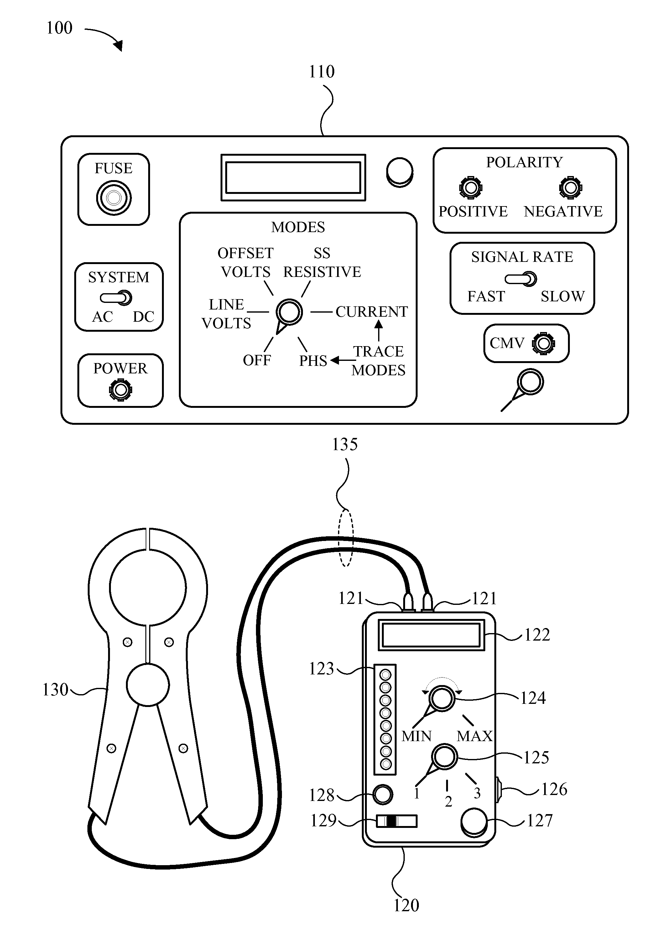
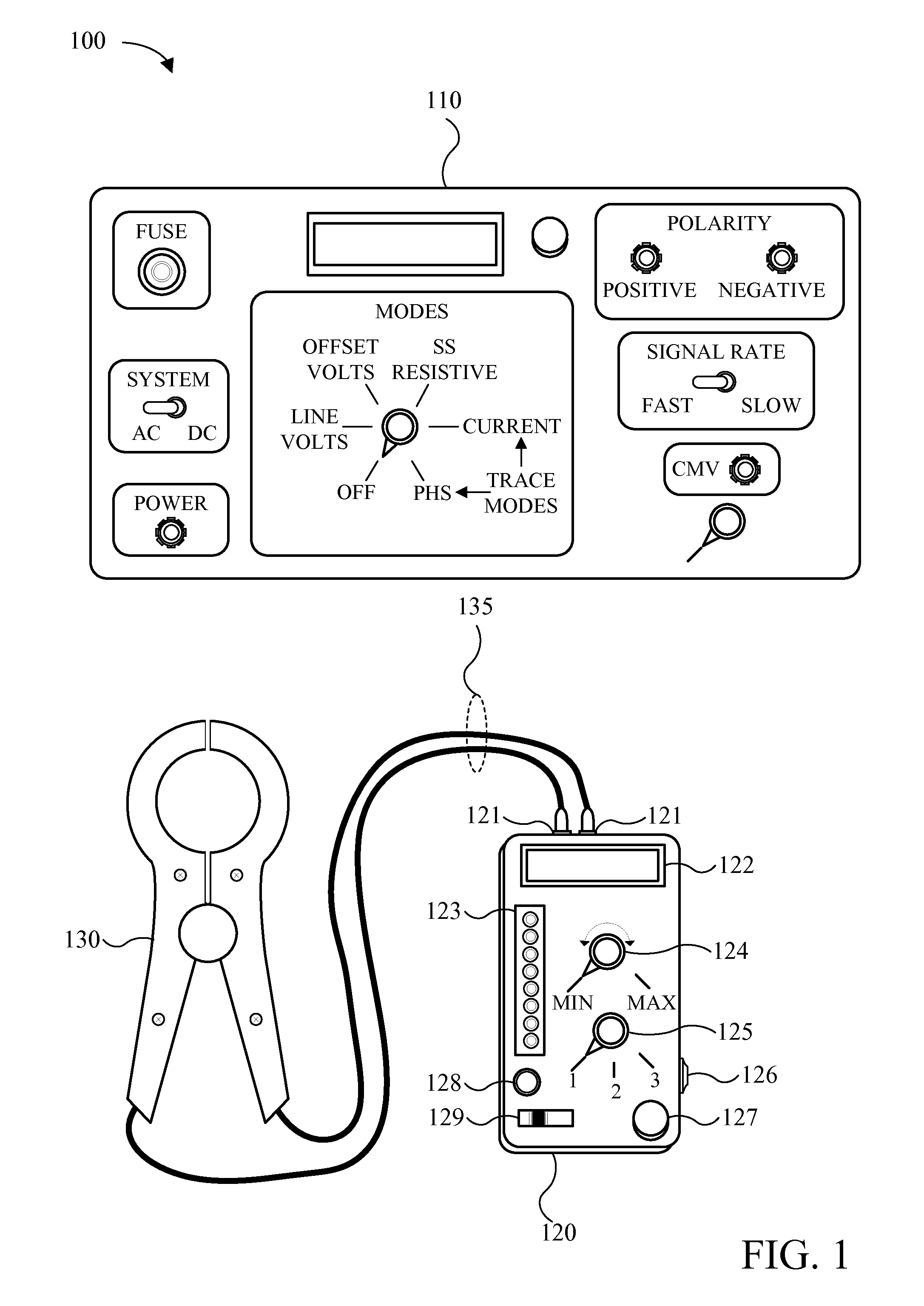
[0033]The apparatus and methods of the most preferred embodiments of the present invention are configured to combine ground fault detection principles, ground fault location principles, circuit isolation principles, and current transformer principles to systematically detect and locate the source of a ground fault on an ungrounded electrical distribution system. The various preferred embodiments of the present invention provide for enhanced ground fault detection, monitoring, and evaluating methods using a permanently mounted detector relay and a separate detection / location device that can be deployed as a portable ground fault detection and location system or as a permanently or semi-permanently mounted ground fault detection and location system.

[0034]In addition, it should be noted that the terms “electrical system,” electrical distribution system” and “system” may be used herein to refer to practically any ungrounded electrical system, including ungrounded alternating current (AC...


PUM


Abstract

The present invention is implemented by deploying an enhanced ground fault detection and location apparatus and by using the apparatus in conjunction with specific circuit analysis methods, using the information generated by the ground fault detection and location apparatus. The ground fault detection and location apparatus comprises the functionality of a voltmeter, an ammeter, a phase angle meter, a frequency generator, and a variable power supply, thereby providing for a variety of signals and analyses to be performed on a unintentionally grounded circuit in an ungrounded AC or DC power distribution system. The ground fault detection and location apparatus is capable of operating in six different modes, with each mode providing a different capability or opportunity for detecting, analyzing, and locating one or more unintentionally grounded circuits in an normally ungrounded AC or DC power distribution system. Additionally, the present invention is configured to manipulate a ground fault current at a first target frequency and a second target frequency, thereby enabling more rapid and efficient location of ground faults.

Description

RELATED APPLICATIONS[0001]This application is a continuation-in-part of U.S. patent application Ser. No. 11 / 504,095 filed on Aug. 10, 2006, which application is now pending and which application is a continuation-in-part of U.S. patent application Ser. No. 10 / 709,146 filed on Apr. 16, 2004, which application is now abandoned, which application is a continuation-in-part of U.S. patent application Ser. No. 10 / 215,310 filed on Aug. 8, 2002, which application is now issued as U.S. Pat. No. 6,844,736, all of which are incorporated herein by reference.BACKGROUND OF THE INVENTION[0002]1. Field of the Invention[0003]The present invention relates generally to detecting and locating ground faults in ungrounded electrical distribution systems and more particularly relates to detecting and locating ground faults without de-energizing the system.[0004]2. Background Art[0005]Most electrical distributions systems that are used to supply power to various types of equipment and machinery are designe...

Claims


Application Information

Patent Timeline
Patent Type & Authority Applications(United States)
IPC IPC(8): G01R31/08
CPCG01R31/08G01R31/025G01R31/52
Inventor WEEMS, II, WARREN A.KINCAID, RUSSSELL L.GREEN, WAYNE L.
Owner WEEMS II WARREN A
Why Eureka
Try Eureka