
Image forming apparatus, surface property reforming sheet, and method for forming image

a surface property and reforming sheet technology, applied in the field of image forming apparatus, can solve the problems of difficult adhesion and achieve the effects of preventing adhesion between the surface property reforming sheet and the thermal transfer sheet, eliminating insufficiency in durability, and good quality

Active Publication Date: 2009-10-15
SONY CORP
View PDF6 Cites 6 Cited by
  • Summary
  • Abstract
  • Description
  • Claims
  • Application Information

AI Technical Summary

Benefits of technology

The present invention relates to an image forming apparatus and method that includes a surface property reforming sheet for protecting the image formed on a recording medium. The invention aims to prevent adhesion between the surface property reforming sheet and the thermal transfer sheet during the surface property reforming treatment, which can lead to defective peeling after the treatment. The invention proposes a non-adhesion treatment layer on at least one surface of the surface property reforming sheet to prevent adhesion. This ensures that the unreleased portion of the protective material layer formed on the thermal transfer sheet does not transfer to the surface property reforming sheet during the treatment. The invention also includes a method for forming an image by aligning the image printing opening of the surface property reforming sheet with the image formation position of the recording medium to be recorded. This allows for precise peeling of the surface property reforming sheet and the thermal transfer sheet after the treatment.

Problems solved by technology

Consequently, in the surface property reforming treatment of the protective layer, even when a used part of the protective material layer (or ink layer) formed on the thermal transfer sheet and the surface property reforming sheet are stacked and subjected to a pressure and heat treatment, adhesion does not occur easily.

Method used


Image

  • Image forming apparatus, surface property reforming sheet, and method for forming image
  • Image forming apparatus, surface property reforming sheet, and method for forming image
  • Image forming apparatus, surface property reforming sheet, and method for forming image

Examples


Embodiment Construction

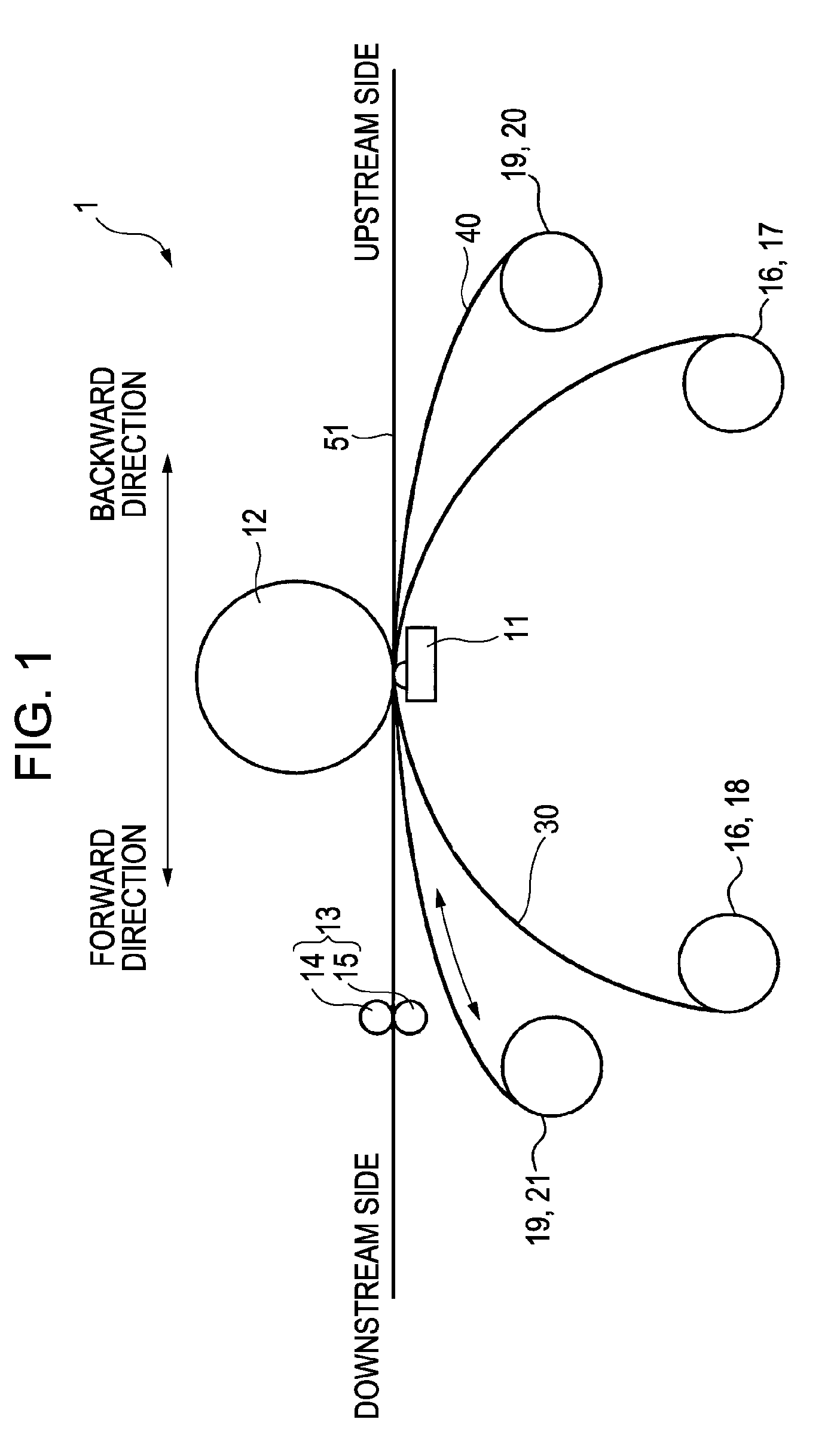
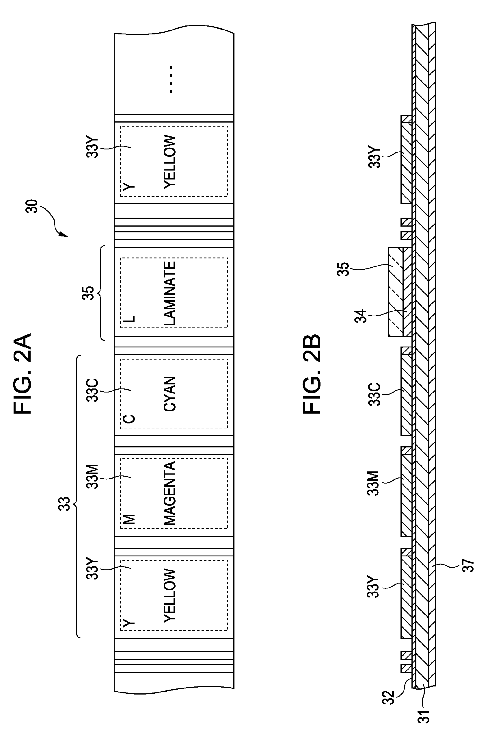
[0045]An example of an embodiment according to the present invention will be described with reference to a schematic configuration diagram of a key portion of an image forming apparatus, as shown in FIG. 1, and a plan view and a sectional view of an ink ribbon, as shown in FIGS. 2A and 2B. FIG. 1 shows a sublimation thermal printer as an example of an image forming apparatus.

[0046]As shown in FIG. 1 and FIG. 2, the key portion of an image forming apparatus 1 includes a thermal head 11 for thermally transferring an ink layer 33 or a protective material layer 35 of a thermal transfer sheet 30 to a surface of a recording medium to be recorded 51. In general, the above-described thermal transfer sheet 30 is also referred to as an ink ribbon. The explanations hereafter will be made on the assumption that it is an ink ribbon. Furthermore, for example, a recording sheet is used as the recording medium to be recorded 51. The explanations hereafter will be made on the assumption that it is a...


PUM

PropertyMeasurementUnit
temperatureaaaaaaaaaa
thicknessaaaaaaaaaa
temperatureaaaaaaaaaa

Abstract

An image forming apparatus includes a feeding device feeding a recording medium to be recorded, a thermal transfer sheet having an ink layer to form an image and a protective material layer to form a protective layer protecting the image, a thermal transfer sheet transporting device, a surface property reforming sheet having an image printing opening disposed in such a way that the thermal transfer sheet comes into direct contact with a surface of the recording medium to be recorded and a surface property reforming portion to reform the surface state of the protective layer protecting the image, a reforming sheet moving device, and a thermal head to thermally transfer the ink layer or the protective material layer, wherein a non-adhesion treatment layer is formed on at least a surface of the surface property reforming sheet on the side to come into contact with the thermal transfer sheet.

Description

BACKGROUND OF THE INVENTION[0001]1. Field of the Invention[0002]The present invention relates to an image forming apparatus, a surface property reforming sheet, and a method for forming an image.[0003]2. Description of the Related Art[0004]In related art at present, leading examples of thermal line printers include sublimation type, fusion type, and heat sensitive type printers.[0005]In thermal heads used in the above-described printers, a plurality of heater elements (resistance elements) are arranged in a line. The plurality of heater elements are energized selectively in accordance with levels of gray scale, and image printing is conducted on various types of recording sheet through the use of the thermal energy generated at that time.[0006]Regarding the sublimation type, image printing is conducted by holding an ink ribbon and a recording sheet fed to a platen with a thermal head, energizing and driving heater elements in the thermal head selectively, and sublimating an ink on t...

Claims


Application Information

Patent Timeline
Patent Type & Authority Applications(United States)
IPC IPC(8): B41J2/335B41M5/40
CPCB41J2202/33B41J2/325
Inventor MURAKAMI, TAKAAKI
Owner SONY CORP
Learn More