

Measuring method, adjustment method for stage movement characteristics, exposure method, and device manufacturing method
a technology of stage movement and adjustment method, applied in the direction of photomechanical equipment, instruments, printers, etc., can solve the problem of taking a long time to perform exposure and mark measurement, and achieve the effect of shortening the tim
- Summary
- Abstract
- Description
- Claims
- Application Information
AI Technical Summary
Benefits of technology
Problems solved by technology
Method used
Image


Examples
first embodiment
[0107]Note that in the first embodiment described above, a plurality of shots 100 is transferred before a plurality of shots 101 is transferred. However, the order of the transferring the shots 100 and 101 can be reversed. That is, a plurality of shots 101 can be transferred before a plurality of shots 100 is transferred.
second embodiment
[0108]Next, a second embodiment according to the present invention is described with reference to FIGS. 6, 7, and 8.
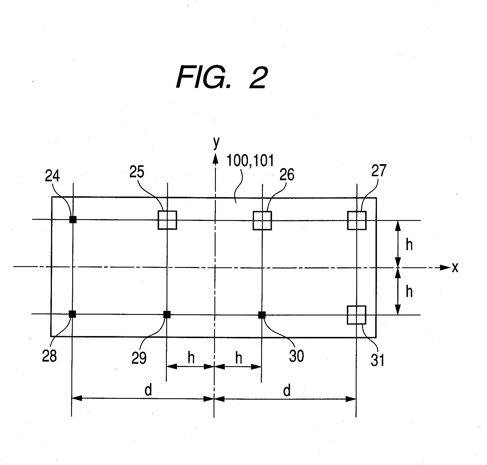
[0109]In the second embodiment, there is used a shot 102 of the pattern image in which the hollow box mark and the solid box mark are changed without changing the arrangement locations of the marks as for marks 47, 48, 49, and 50 illustrated in FIG. 6, with respect to the shot 100 of the pattern image illustrated in FIG. 2. In addition, as illustrated in FIGS. 7 and 8, a step width in the arrangement of the shots 102 and 103 in the x direction and the y direction are both set to be 2d in each of the first exposure and the second exposure. In this case, as illustrated in FIG. 7, a shot 51 transferred in the second exposure crosses a shot 52 transferred in the first exposure so that a superimposed region is formed. The shots 52 and 53 transferred in the first exposure form a superimposed region with each short side. This means that the step widths of the shots 102 and 10...
third embodiment
[0111]Next, the present invention is described with reference to FIGS. 9, 10, and 11.
[0112]In the third embodiment, marks 54, 55, 56, and 57 are added at locations having a distance (d−h) in the x direction from the center position of the pattern image shot 104 as illustrated in FIG. 9 with respect to the pattern image shot 100 illustrated in FIG. 2. Further, as illustrated in FIGS. 10 and 11, marks 104 transferred in the first exposure and marks 105 transferred in the second exposure are arranged so as to overlap each other. In other words, the step widths in the arrangement of the shots 104 and 105 in the x direction and the y direction are both 2d in each of the first exposure and the second exposure. Also in this case, the step widths of the shots 104 and 105 in the x direction and the y direction are 2d in each of the first exposure and the second exposure. Therefore, if the step width of the shot arrangement to be determined is the same constant value in the x direction and th...
PUM
 Abstract
Description
Claims
Application Information