
Artifact suppression in multi-coil MRI

a multi-coil, artifact technology, applied in the field of magnetic resonance imaging system, can solve the problems of inability to perform inability to achieve pre-saturation in other than straight slabs, and inability to achieve high-quality magnetic resonance images. achieve the effect of high-quality magnetic resonance images

Active Publication Date: 2009-10-15
KONINKLIJKE PHILIPS ELECTRONICS NV
View PDF2 Cites 7 Cited by
  • Summary
  • Abstract
  • Description
  • Claims
  • Application Information

AI Technical Summary

Benefits of technology

[0007]It is the object of the present invention to provide a magnetic resonance imaging system as well as a method of the above-mentioned type which enable obtaining high-quality magnetic resonance images from an object, e.g. a patient, which do not suffer from artefacts caused by any kind of instability, e.g. motion or other local effects, which occur with respect to a limited portion of an object under study, and which are not bound to geometrical restrictions.SUMMARY OF THE INVENTION
[0009]According to a second aspect of the present invention the object is achieved by providing a computer program product of the above-mentioned type which comprises further code sequences for implementing a mechanism for combining magnetic resonance signal contributions from respective receiving units in such a way that a combined sensitivity of the plurality of receiving units to a predetermined spatial region of the object is reduced.

Problems solved by technology

However, said technique is often bound to geometrical restrictions, because performing pre-saturation in regions other than straight slabs is usually impractical.
Furthermore, the above-described prior art approach suffers from serious drawbacks in terms of scan time, attainable repetition rate, etc.

Method used


Image

  • Artifact suppression in multi-coil MRI
  • Artifact suppression in multi-coil MRI
  • Artifact suppression in multi-coil MRI

Examples


Embodiment Construction

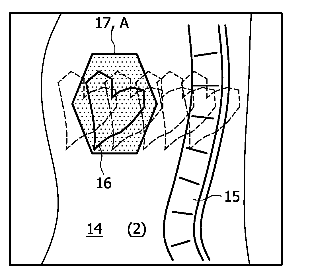
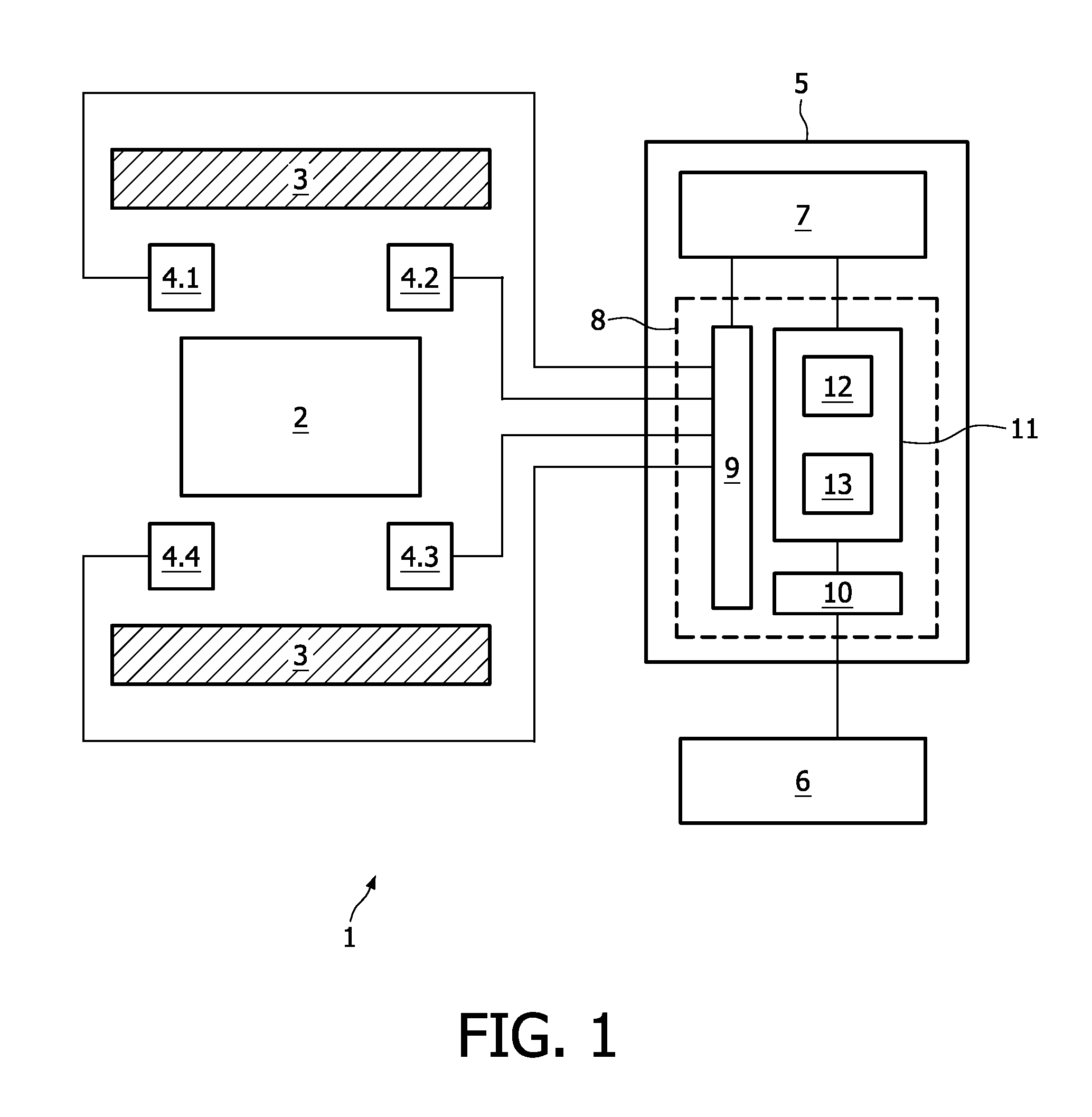
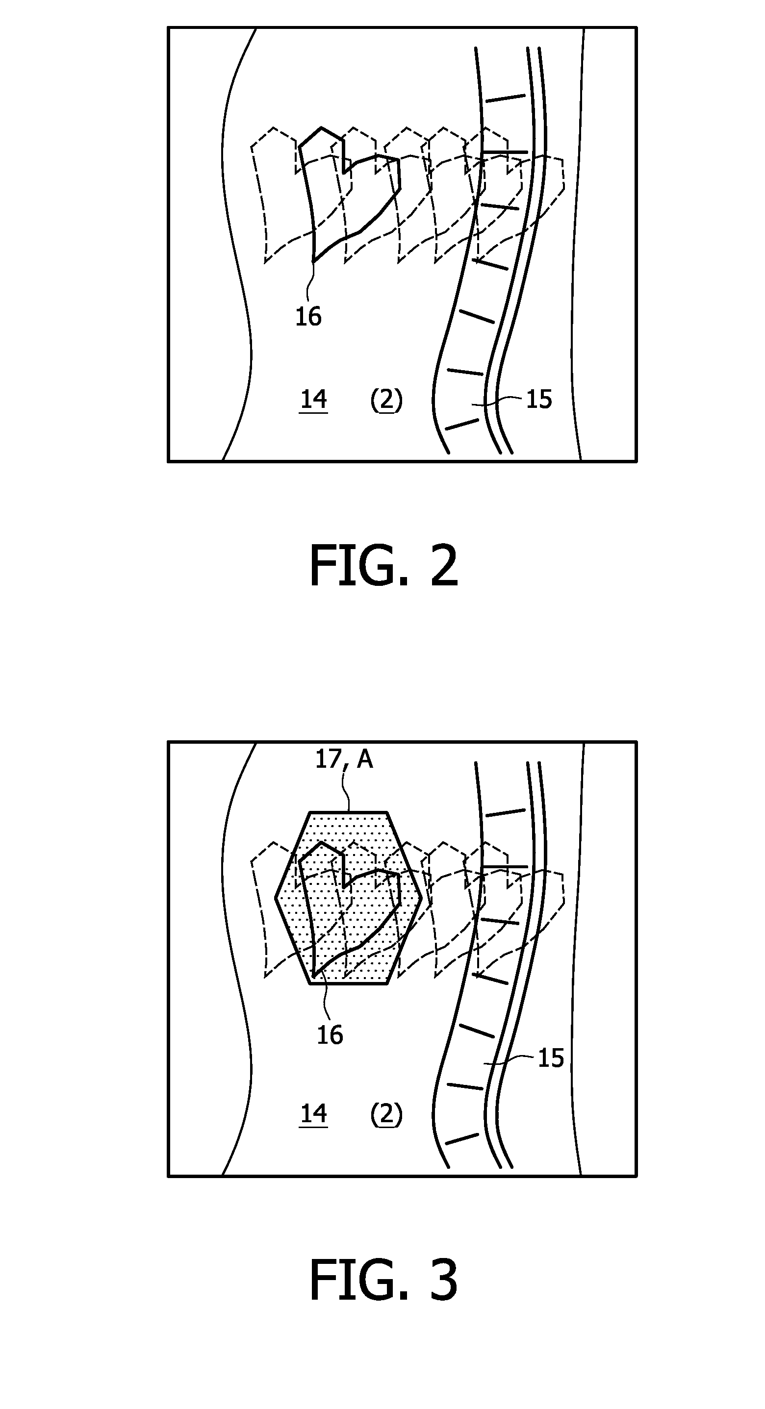
[0030]FIG. 1 shows a block diagram of a magnetic resonance imaging system 1 in accordance with the present invention. For providing magnetic resonance images of an object 2, e.g. a patient, said system 1 comprises a main magnet 3 producing a strong magnetic field in which object 2 is placed for magnetic resonance imaging, as known to a person skilled in the art. Said magnetic field is a uniform magnetic field that causes an alignment of the moments of magnetic spin of atoms contained within the object. As further known to a person skilled in the art, system 1 further comprises a number of functional units (not shown) that apply a transverse magnetic field, generated by radio frequency (RF) pulses, to the object such that the aligned moments rotate or tip, thereby exciting the spins of the atoms. The excited spins of the atoms generate a magnetic resonance signal that is detected by a plurality of receiving units 4.1-4.4 (receiving or imaging coils) comprised within the magnetic reso...


PUM


Abstract

A magnetic resonance imaging system (1), comprising a plurality of receiving units (4.1-4.4) for receiving magnetic resonance signals from an object (2), and an image reconstruction device (8), said image reconstruction device being adapted to receive magnetic resonance signals of said object (2) from said plurality of receiving units (4.1-4.4) and to perform image reconstruction by combining magnetic resonance signals received by said plurality of receiving units using an image reconstruction algorithm (11), characterised in that said image reconstruction device (8) comprises means (12a) for combining magnetic resonance signal contributions from respective receiving units (4.1-4.4) in such a way that a combined sensitivity of the plurality of receiving units (4.1-4.4) to a predetermined spatial region of the object (2) is reduced.

Description

BACKGROUND OF THE INVENTION[0001]The present invention relates to a magnetic resonance imaging system, comprising a plurality of receiving units for receiving magnetic resonance signals from an object, further comprising an image reconstruction device, said image reconstruction device being adapted to receive magnetic resonance signals of said object from said plurality of receiving units and to perform image reconstruction by combining magnetic resonance signals received by said plurality of receiving units using an image reconstruction algorithm.[0002]The present invention also relates to a method of image reconstruction in a magnetic resonance imaging system, comprising receiving magnetic resonance signals of an object from a plurality of receiving units and performing image reconstruction by combining magnetic resonance signals received by said plurality of receiving units by means of an image reconstruction algorithm.[0003]The present invention further relates to a computer pro...

Claims


Application Information

Patent Timeline
IPC IPC(8): G06K9/40G06K9/00
CPCG01R33/56509G01R33/3415
Inventor FUDERER, MIHA
Owner KONINKLIJKE PHILIPS ELECTRONICS NV
Learn More