Threading method and threading apparatus

a technology of threading apparatus and threading method, which is applied in the field of processing technique for threading a work, can solve the problems of deteriorating efficiency of operation and external appearance of the inlet portion of the female screw, and achieve the effect of improving operation efficiency

Inactive Publication Date: 2009-10-15
HONDA MOTOR CO LTD
View PDF10 Cites 4 Cited by
  • Summary
  • Abstract
  • Description
  • Claims
  • Application Information

AI Technical Summary

Benefits of technology

[0018]Accordingly, it is desired to provide a processing technique which can attain the improved efficiency of the operation.
[0019]An object of the invention is to provide a processing technique which can process a screw with improved efficiency of the processing.
[0039]a lower limit stopper which restricts a lower movable range of the tap.
[0040]According to the aspect of the invention, only the supporting portion is moved upward by the predetermined distance without rotating or elevating the tap. Thus, the bent state of the robot arm can be eliminated by moving the supporting portion upward. In this case, since the supporting portion is forcedly moved upward by the predetermined distance, the supporting portion can be moved upward in a short time. That is, the bent state of the robot arm can be eliminated in a short time and hence the efficiency of the threading step can be improved.
[0041]According to another aspect of the invention, the tap is supported so as to be movable freely with respect to the processing direction. Thus, the bent state of the robot arm is eliminated by only moving the supporting portion. Therefore, the tap is prevented from contacting again with the female screw hole by such a simple apparatus.
[0042]According to the still another aspect of the invention, the upper limit stopper and the lower limit stopper are disposed. The upper movable range and the lower movable range of the tap are restricted by disposing the stoppers. The tap can receive a force of the elevational mechanisms since the upper limit is defined, and the tap can be firmly supported by the supporting portion in a state that the tap does not contact with a work since the lower limit is defined. Further, the tap can be prevented from being excessively moved upward or downward. In this manner, the tap can be moved elevationally in a suitable range and so the operability of the apparatus can be improved.

Problems solved by technology

When the tap contacts with the inlet portion, the tap wears away the inlet portion of the work, so that the external appearance of the inlet portion of a female screw is deteriorated.
The efficiency of the operation is deteriorated since it is required to wait until the bent state disappears depending on the force for eliminating the bent state.

Method used


Image

  • Threading method and threading apparatus
  • Threading method and threading apparatus
  • Threading method and threading apparatus

Examples


Embodiment Construction

[0056]Embodiments of the invention will be explained with reference to attached drawings. Each of the drawings is supposed to be seen according to the direction of symbols.

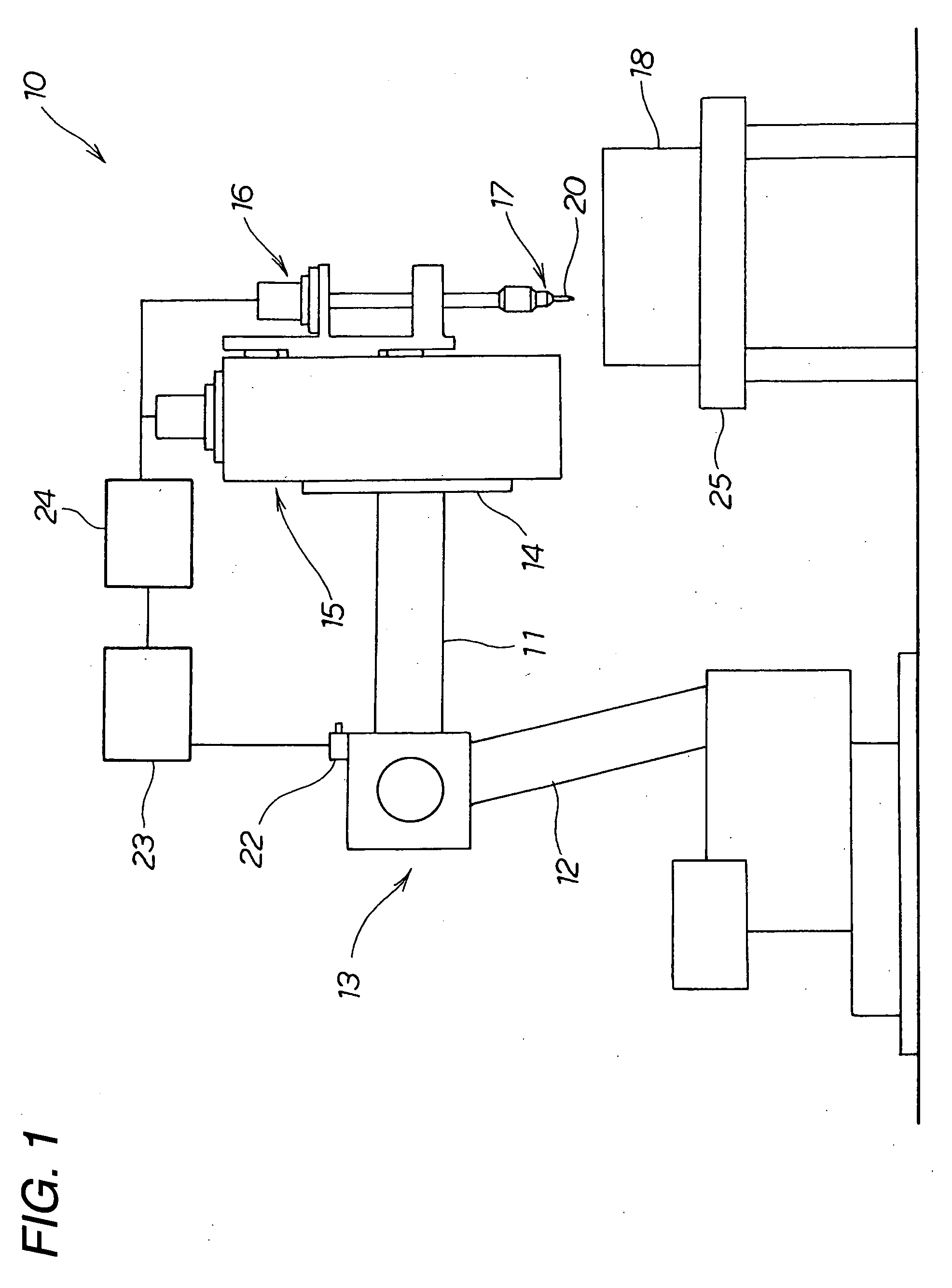
[0057]FIG. 1 is a side view showing a threading apparatus 10 according to the invention.

[0058]The threading apparatus 10 has:

[0059]a robot 13 which has a robot arm 11 disposed at a tip end thereof and operates a positioning arm 12 to determine a threading position for forming a female screw;

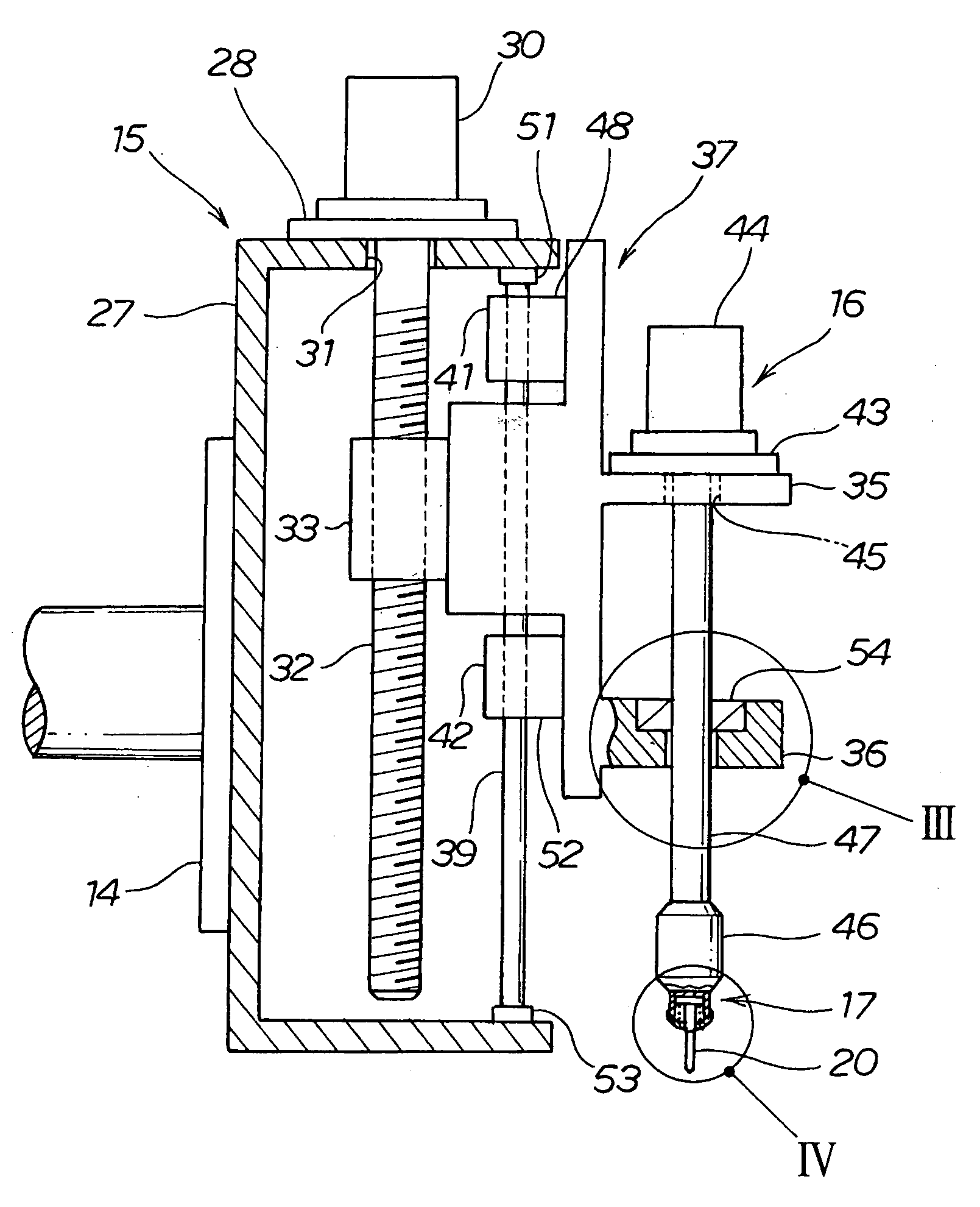
[0060]an elevational mechanism 15 which is supported via a flange 14 at the tip end of the robot arm 11;

[0061]a rotational mechanism 16 which is supported by the elevational mechanism 15;

[0062]a supporting portion 17 disposed at the tip end of the rotational mechanism 16;

[0063]a tap 20 which is supported by the supporting portion 17 and threads to form a female screw at a work 18;

[0064]a sensor 22 which is disposed on the upper surface of the robot 13 and detects the inclination of the robot arm 11;

[0065]a calculation unit 23 w...


PUM

PropertyMeasurementUnit
distanceaaaaaaaaaa
reaction forceaaaaaaaaaa
rotationaaaaaaaaaa

Abstract

A threading method for threading a work 18 includes a supporting portion moving-up step for moving a supporting portion 17 upward by a predetermined distance by using an elevational mechanism 15 without rotating a tap 20 inserted into the work 18. Thus, the bent state of the robot arm 11 can be eliminated by moving the supporting portion 17 upward. In this case, since the supporting portion 17 is moved upward artificially, the supporting portion 17 can be moved up in a short time. That is, the bent state of the robot arm 11 can be eliminated in a short time and so the processing efficiency of the threading step can be improved.

Description

BACKGROUND OF THE INVENTION[0001]1. Field of the Invention[0002]The present invention relates to a processing technique for threading a work.[0003]2. Description of Related Art[0004]When forming a female screw at a work, the female screw is sometimes formed by using a threading apparatus. A tap is lowered while being rotated to form the female screw. The tap is rotated reversely and removed from the work after forming the female screw.[0005]When forming a female screw by using a tap, reaction force is imparted to a member for supporting the tap. The member for supporting the tap bends due to the reaction force. Although the bent state disappears when the tap is removed from the work, the complete thread portion of the tap may contact with an inlet portion of the hole of the female screw due to the reaction at the time of the disappearance of the bent state. When the tap contacts with the inlet portion, the tap wears away the inlet portion of the work, so that the external appearance...

Claims


Application Information

Patent Timeline
Patent Type & Authority Applications(United States)
IPC IPC(8): B23B35/00B23B47/20
CPCB23G1/18B23G2240/36Y10T408/03Y10T408/18B23G2240/52
Inventor TAKAHASHI, NAOKIFUJIUCHI, HIROKIEGUCHI, YOTAHIRUMA, YOSUKE
Owner HONDA MOTOR CO LTD
Why Eureka
Try Eureka