Electric compressor

Active Publication Date: 2009-10-15
HONDA MOTOR CO LTD
View PDF0 Cites 13 Cited by
  • Summary
  • Abstract
  • Description
  • Claims
  • Application Information

AI Technical Summary

Benefits of technology

[0009]An object of the present invention is to improve an electric compressor, and more specifically to provide an electric compressor which enables reduc

Problems solved by technology

However, because the pressure of gas corresponding to the thrust load acts on the load cancellation portion in the direction opposite thereto, the thrust load generated a

Method used


Image

  • Electric compressor
  • Electric compressor
  • Electric compressor

Examples


Example

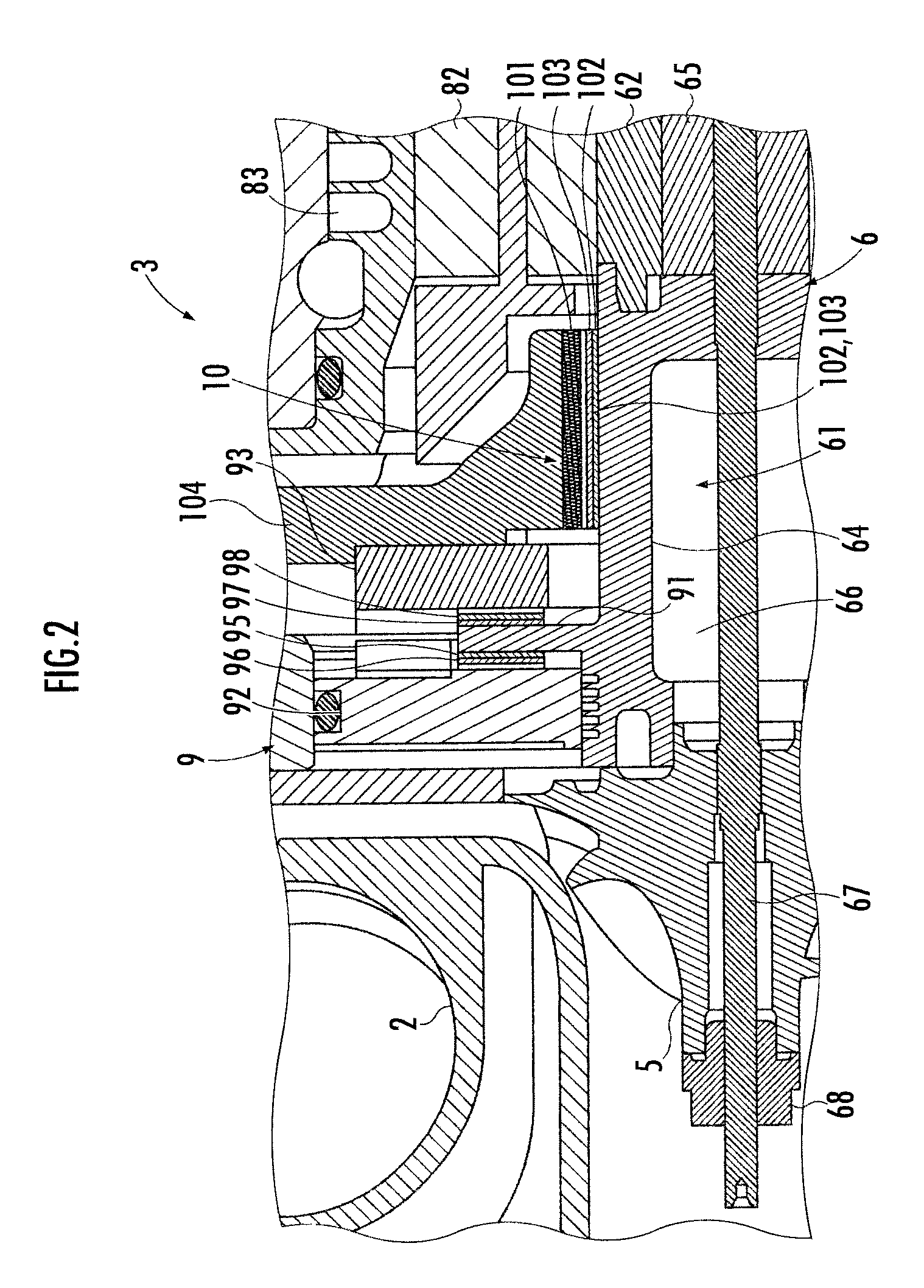
[0017]Hereinafter, an electric turbo compressor as an embodiment of an electric compressor of the present invention will be now explained with reference to FIG. 1 through FIG. 3. FIG. 1 is an explanatory cross-sectional view of an electric turbo compressor of the present embodiment, FIG. 2 is an enlarged view of a thrust bearing portion in FIG. 1, and FIG. 3 is a graph showing a relationship between a thrust load and the like generated at the rotary shaft and the number of rotations.

[0018]An electric turbo compressor 1 of the present embodiment is an air compressor used in a fuel cell system. As shown in FIG. 1, the electric turbo compressor 1 includes a housing comprised of a compression casing 2, a motor casing 3, and a canceller casing 4, the housing houses therein an impeller 5, a rotary shaft 6, a thrust canceller (a load cancellation section) 7, and a motor unit 8. Further, the rotary shaft 6 is supported by a thrust air bearing 9 in its thrust direction. Still further, the ro...


PUM


Abstract

An electric turbo compressor is an air compressor to be used in a fuel cell system, and includes a housing comprised o a compression casing, a motor casing, and a canceller casing, and the housing houses therein an impeller, a rotary shaft, a thrust canceller (a load cancellation section), and a motor unit. The rotary shaft is supported by a thrust air bearing in its thrust direction, and is axially supported by a radial air bearing in its rotating direction. A thrust load is generated at the rotary shaft when the number of rotations of the impeller increases. The pressure of the compressed air acts to the pressure chamber from the compressed air lead-out section of the compression casing via the compressed air passage, and this pressure acts on the canceller flange of the canceller shaft so as to generate a load towards the rear of the rotary shaft. Therefore, the thrust load is cancelled out.

Description

BACKGROUND OF THE INVENTION[0001]1. Field of the Invention[0002]The present invention relates to an electric compressor which compresses gas with the rotation of an impeller, by rotating a rotary shaft and the impeller with a motor unit.[0003]2. Description of the Related Art[0004]In the conventional electric compressor, for example, there is disclosed a turbo machine equipped with vane wheels (hereinafter referred to as impellers) to both sides of the rotary shaft, in Japanese Patent Laid-Open No. H11-13686 (hereinafter referred to as Patent Document 1). Generally, in this type of compressor, a thrust load proportional to a square of a number of rotations of the impeller generates in the axial direction of the rotary shaft, when the number of rotations of the impeller increases. In the turbo machine disclosed in Patent Document 1, the thrust load is cancelled by making the thrust load generated by the impellers provided to both sides of the rotary shaft to act in a direction opposi...

Claims


Application Information

Patent Timeline
IPC IPC(8): F04D29/051F01D3/02
CPCF04D29/051F04D29/0513F04D29/0516F04D29/057F16C17/024F16C17/042F16C2360/44
Inventor TAKADO, JUNJISATO, TAKAHARU
Owner HONDA MOTOR CO LTD
Why Eureka
Try Eureka