Using telemetry coupling as a surrogate for recharger coupling

a recharger and telemetry technology, applied in the field of imds, can solve the problems of inconvenient continuous coupling of patients to external power sources, disadvantageous electrical wires perforating the skin, and single cell batteries usually do not supply the lasting power required

Active Publication Date: 2009-10-15
MEDTRONIC INC
View PDF7 Cites 65 Cited by
  • Summary
  • Abstract
  • Description
  • Claims
  • Application Information

AI Technical Summary

Benefits of technology

[0021]A telemetry signal strength map for use with the current invention may be created in several ways. According to a first approach, it may be created empirically. During this empirical process, the antenna of the recharging unit is systematically positioned at various locations relative to the IMD while telemetry signal strength measurements and corresponding recharging coupling measurements are obtained. This information may then be stored as a data set within the signal strength map. This process may occur prior to implant or after implant of the IMD. In another embodiment, the process of collecting and associating telemetry signal strength measurements with recharging coupling efficiency measurements may be repeated at regular intervals. For instance, new measurements may be taken every Nth time the signal strength map is used, where N is programmable. This allows the signal strength map to be adaptive. That is, the signal strength map will be modified over time to take into account changes that occur in the circuitry of the IMD (e.g., as the battery ages) and / or within the patient's body.

Problems solved by technology

However, having electrical wires that perforate the skin is disadvantageous due, in part, to the risk of infection.
Further, continuously coupling patients to an external power source for therapy is a large inconvenience.
However, such single cell batteries usually do not supply the lasting power required to perform therapies provided by newer IMDs.
First, the inductive coupling has a tendency to heat surrounding components and tissue.
Since it is desirable to limit this heating effect, the amount of energy transfer per unit time must also be limited.
This attachment may impair the patient's mobility and limit the patient's comfort.
Finally, the amount of energy available to the IMD may be limited by the amount of time the patient is willing to devote to recharging the device.
However, because the loading of the system is affected by non-device metallic objects in the vicinity of the device, false results can be produced, resulting in non-optimal alignment.
Thus, finding the optimal location may take a substantial amount of time.

Method used


Image

  • Using telemetry coupling as a surrogate for recharger coupling
  • Using telemetry coupling as a surrogate for recharger coupling
  • Using telemetry coupling as a surrogate for recharger coupling

Examples


Embodiment Construction

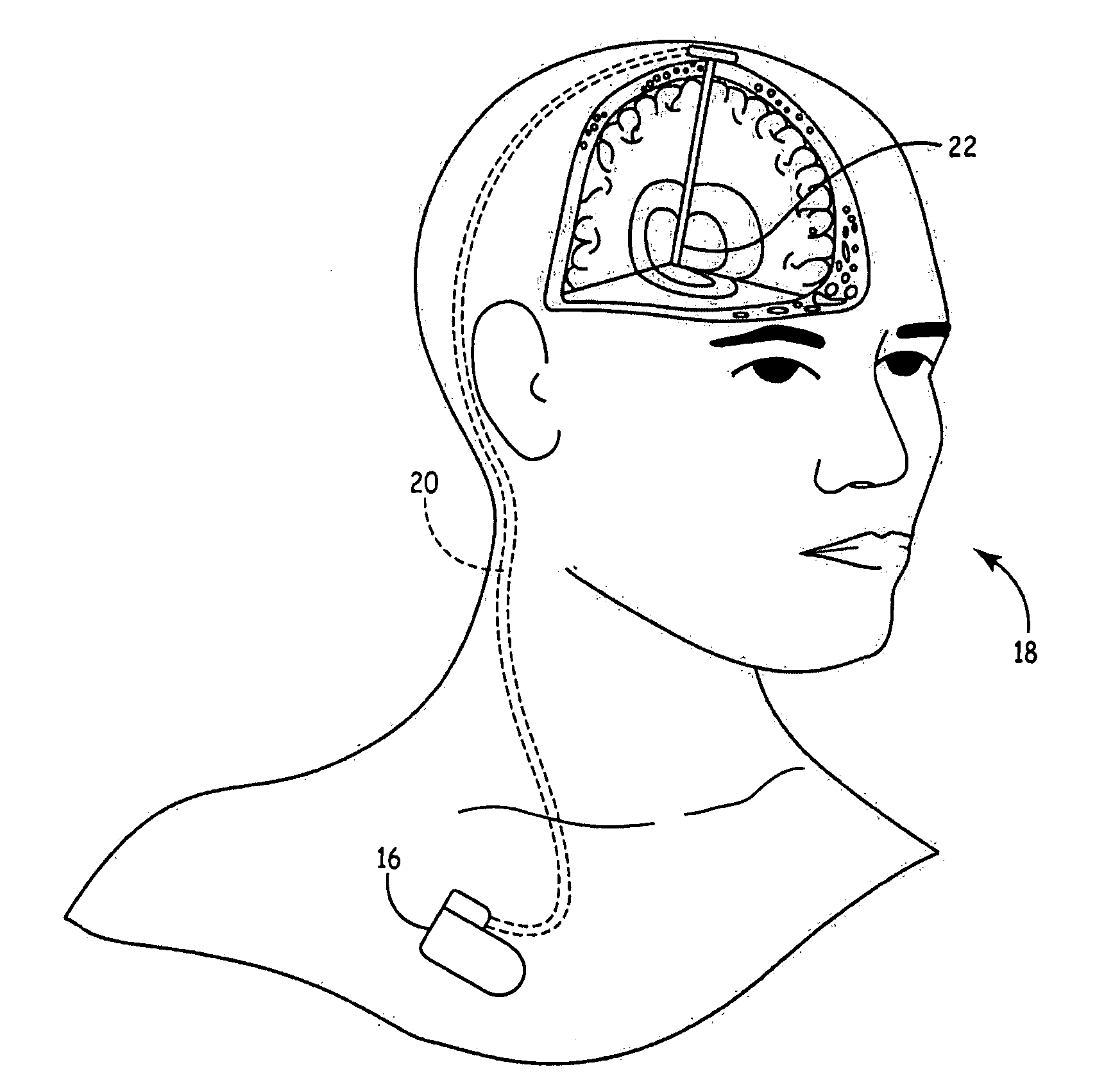
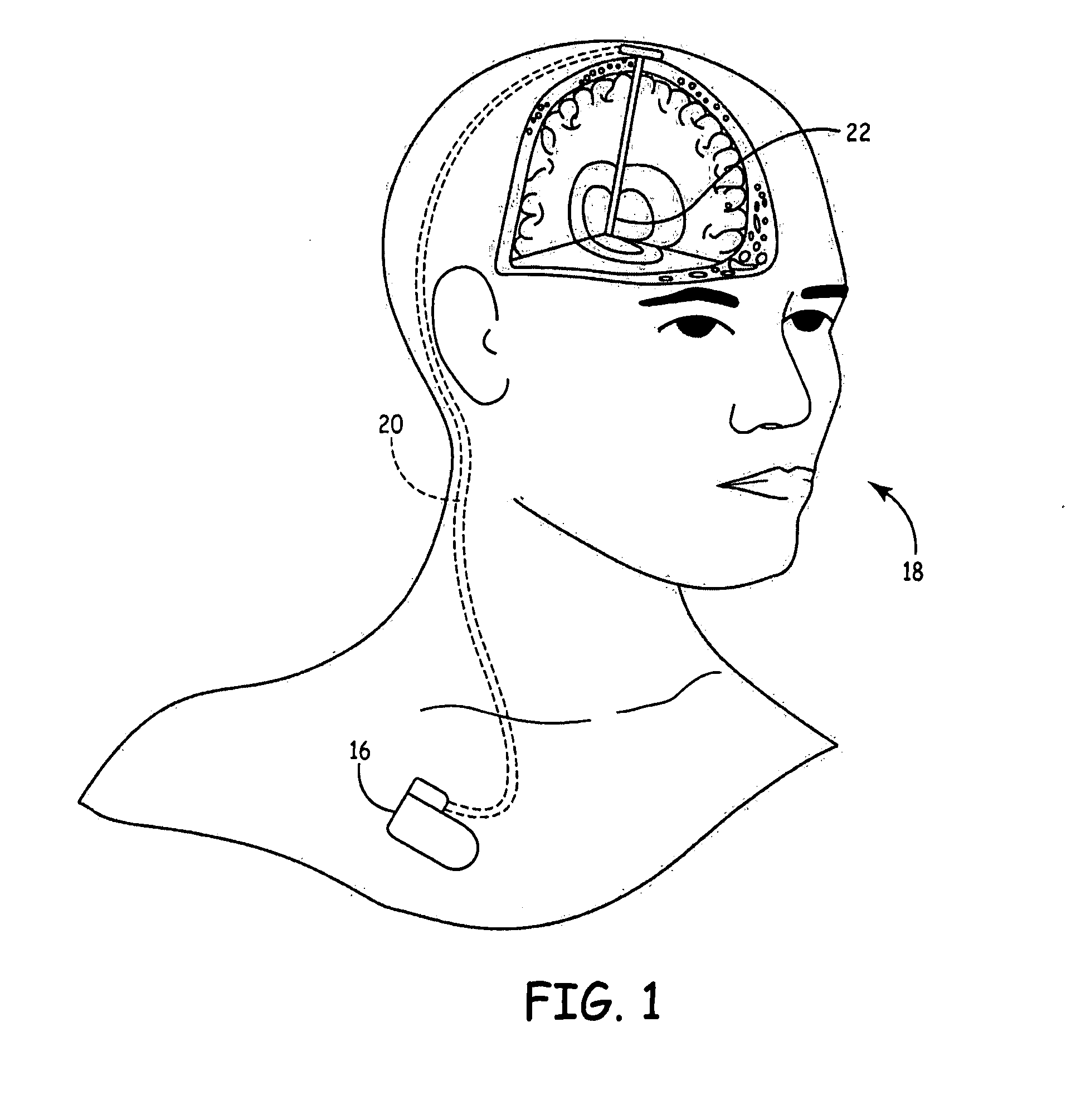
[0041]FIG. 1 shows an exemplary IMD 16, which may be a neurostimulator, implanted in patient 18. IMD 16 can be any of a number of medical devices such as an implantable therapeutic substance delivery device, implantable drug pump, cardiac pacemaker, cardioverter or defibrillator, a device to delivery electrical stimulation pulses for a neurological or muscular condition or to alleviate pain, or any other IMD for delivering therapy.

[0042]The IMD 16 is typically implanted by a surgeon in a sterile surgical procedure performed under local, regional, or general anesthesia. One or more therapy connections 20 such as leads or catheters are typically implanted with a distal end positioned at a desired therapeutic delivery site 22. In the exemplary embodiment, a proximal end of a therapy connection 20 may be tunneled under the skin to the location where IMD 16 is to be implanted.

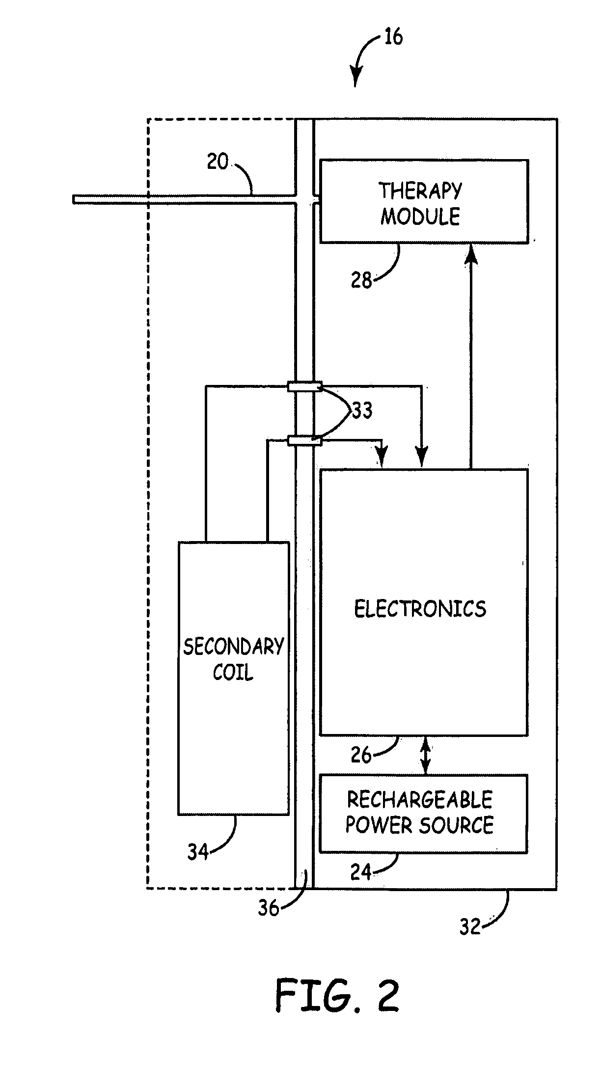
[0043]FIG. 2 is a block diagram of one embodiment of IMD 16. In FIG. 2, IMD 16 includes a rechargeable power sour...


PUM


Abstract

Techniques for using telemetry signal strength for positioning a primary recharge coil of a recharging unit at a location proximate to an Implantable Medical Device (IMD) in preparation to recharge a rechargeable power source of the IMD are disclosed. An antenna of the recharging unit is positioned proximate to the IMD, a telemetry session is initiated between the two devices, and a value indicative of the telemetry signal strength is obtained. Using a known correspondence between telemetry signal strength and recharge coupling efficiency for the IMD / recharging unit pair, the telemetry signal strength value is used to determine whether adequate recharge coupling may be achieved between the pair of devices. If so, a recharge session may be established. Otherwise, the antenna is repositioned and the process is repeated. The correspondence between telemetry signal strength and recharge coupling efficiency for the device pair may be developed empirically or using modeling.

Description

FIELD OF THE INVENTION[0001]This invention relates to IMDs and, in particular, to energy transfer devices, systems and methods for IMDs.BACKGROUND OF THE INVENTION[0002]Implantable Medical Devices (IMDs) for producing a therapeutic result in a patient are well known. For example, implantable neurostimulators are available for the treatment of pain, movement disorders such as Parkinson's disease, essential tremor, dystonia, gastric disorders, incontinence, sexual disfunction, migraine headaches, and other conditions. Other examples of IMDs include, but are not limited to, implantable drug infusion pumps, cardioverters, cardiac pacemakers, defibrillators, and cochlear implants.[0003]All of the foregoing types of IMDs require electrical power to perform their therapeutic function, which may include driving an electrical infusion pump, providing an electrical neurostimulation pulse, or providing an electrical cardiac stimulation pulse. This electrical power is derived from a power sourc...

Claims


Application Information

Patent Timeline
Patent Type & Authority Applications(United States)
IPC IPC(8): A61N1/375
CPCA61N1/378A61N1/37252A61N1/3787
Inventor FIGUEIREDO, GISELLE SURAYAFORSBERG, JOHN W.KEACHER, JEFFREY T.TOY, ALEX C.WIDMAN, ERIK G.
Owner MEDTRONIC INC
Why Eureka
Try Eureka