
In-cylinder fuel-injection type internal combustion engine, piston for in-cylinder fuel-injection type internal combustion engine and process for manufacturing piston for in-cylinder fuel-injection type internal combustion engine

a technology of in-cylinder fuel injection and internal combustion engine, which is applied in the direction of valve arrangement, machines/engines, pistons, etc., can solve the problems of obstructing the heat transfer from the low thermal conductor, not easy to always atomize or vaporize the fuel fully, and fuel consumption might have degraded, etc. , to achieve the effect of good heat insulation property, reducing thermal conductivity, and reducing the amount of exhaust gas

Inactive Publication Date: 2009-10-22
TOYOTA JIDOSHA KK
View PDF14 Cites 12 Cited by
  • Summary
  • Abstract
  • Description
  • Claims
  • Application Information

AI Technical Summary

Benefits of technology

The present invention relates to a piston for in-cylinder fuel-injection type internal combustion engines. The piston has a low thermal conductor that acts as a fuel collision zone and a coating layer made of alumina fine particles that improves the low thermal conductor's ability to prevent heat transfer. This results in better fuel atomization and purification of exhaust gases. The coating layer is applied by casting the piston and is made of alumina fine particles and aluminum alloy. The piston head is cast burried and the low thermal conductor makes it likely for liquid fuels to atomize or vaporize more reliably. The low thermal conductor acts as a heat insulating layer and the coating layer further enhances the heat insulating property. This improves the engine's performance and fuel consumption. The piston can be manufactured without increasing manufacturing costs.

Problems solved by technology

However, in in-cylinder fuel-injection type internal combustion engine, it is not easy to always atomize or vaporize the fuel fully, because the injection amount and injection timing of fuel that is injected into the cylinders fluctuate depending on loads to the internal combustion engine.
Accordingly, an adverse effect, such as the incomplete combustion of fuel, has arisen, albeit only slightly, so that the fuel consumption might have degraded or the emissions of hydrocarbons and soot might have increased in the exhaust gases, though even temporarily, when cold running the internal combustion engine.
Consequently, it has been likely that such an instance that the exhaust gases are purified insufficiently might occur when cold running the internal combustion engines, that is, immediately after starting them up, for instance.
Consequently, it might be even possible for such insufficient atomization or vaporization to adversely affect making the internal combustion engine consume fuel less and making the exhaust gases clean.
However, according to surveys and studies that the present inventors have carried out so far, it has been found difficult to actually form such a minute-intersticed layer as disclosed in Japanese Patent Gazette No. 3,551,801 when the plate whose rear surface is turned into an irregular shape is simply cast buried or enveloped in the piston with an aluminum-alloy molten metal.
That is, the formation of the minute-intersticed layer is hardly possible because the molten metal flows unstably during the cast burying or enveloping.
Moreover, turning the rear surface of the plate as an irregular shape is likely to result in increased manufacturing costs.
In addition, considering the large explosive forces that act onto the piston, it is impossible to thin out the plate on the rear-surface side or reduce the plate's thickness from the viewpoint of the strength and rigidity.

Method used


Image

  • In-cylinder fuel-injection type internal combustion engine, piston for in-cylinder fuel-injection type internal combustion engine and process for manufacturing piston for in-cylinder fuel-injection type internal combustion engine
  • In-cylinder fuel-injection type internal combustion engine, piston for in-cylinder fuel-injection type internal combustion engine and process for manufacturing piston for in-cylinder fuel-injection type internal combustion engine
  • In-cylinder fuel-injection type internal combustion engine, piston for in-cylinder fuel-injection type internal combustion engine and process for manufacturing piston for in-cylinder fuel-injection type internal combustion engine

Examples


example

[0086]Hereinafter, the present invention will be described in more detail with reference to a specific example.

In-Cylinder Fuel-Injection Type Internal Combustion Engine

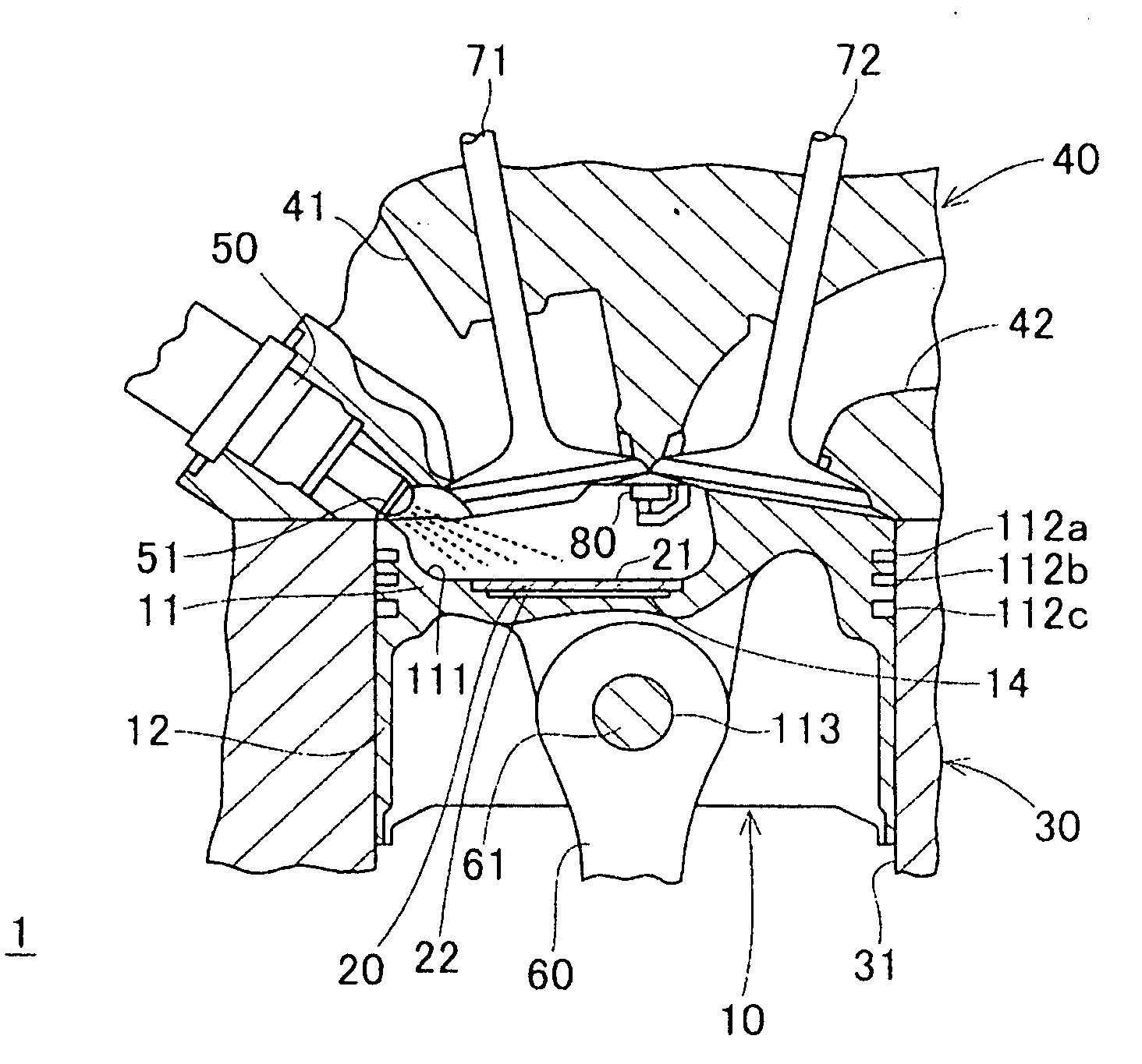
[0087]FIG. 1 illustrates an in-cylinder fuel-injection type spark ignition engine 1 (hereinafter simply referred to as “engine 1”), an example that is directed to an in-cylinder fuel-injection type internal combustion engine according to present invention.

[0088]The engine 1 comprises a cylinder block 30, a cylinder head 40, and a piston 10. The cylinder head 40 is fixed on the cylinder block 30 by way of a not-shown gasket with not-shown head bolts. The piston 10 is fitted into a cylinder 31 of the cylinder block 30 reciprocably.

[0089]The cylinder block 30, the cylinder head 40, and the piston 10 are made of aluminum alloy. For example, the piston 10 is made of AC8A alloy (as per JIS), an aluminum alloy whose thermal conductivity is 134 W / m·K at room temperature and linear-expansion coefficient is 20.9×10⁻⁶ / K in a te...


PUM

PropertyMeasurementUnit
particle diameteraaaaaaaaaa
thicknessaaaaaaaaaa
temperatureaaaaaaaaaa

Abstract

A piston for in-cylinder fuel-injection type internal combustion engine includes a piston body, a low thermal conductor, and a piston head. The low thermal conductor is disposed on the top of the piston body. The low thermal conductor includes a low thermally-conductive substrate, and a coating layer. The low thermally-conductive substrate has opposite surfaces. The coating layer includes alumina fine particles (Al2O3). The coating layer is adhered on at least a part one of the opposite surfaces of the low thermally-conductive substrate that makes a cast-buried or enveloped surface to be cast buried or enveloped in the piston head.

Description

INCORPORATION BY REFERENCE[0001]The present invention is based on Japanese Patent Application No. 2008-106,944, filed on Apr. 16, 2008, the entire contents of which are incorporated herein by reference.BACKGROUND OF THE INVENTION[0002]1. Field of the Invention[0003]The present invention relates to an in-cylinder fuel-injection type internal combustion engine, such as diesel engines and gasoline engines, a piston for in-cylinder fuel-injection type internal combustion engine, piston which is provided with a low thermal conductor for facilitating the atomization or vaporization of liquid fuel that is injected into the internal combustion engine's cylinder, and a process for manufacturing the piston.[0004]2. Description of the Related Art[0005]As environmental consciousness has been growing, it has been required strongly to make internal combustion engines, such as diesel engines and gasoline engines that are used for automobiles, motorcycles and industrial machines, consume fuels less...

Claims


Application Information

Patent Timeline
Patent Type & Authority Applications(United States)
IPC IPC(8): F02F3/00B23P15/10
CPCB23P15/10F02F3/0084F02F3/14F02F3/26F05C2201/0412Y10T29/49249F05C2201/0487F05C2201/903F05C2203/0808F05C2203/0869B22D19/0027F05C2201/0436
Inventor HARA, MASASHIITOH, KAZUHIKOKONDOH, MIKIONISHINO, KAZUAKIUEDA, ISAMUANDO, KIMIHIKOITO, YOSHIHIKO
Owner TOYOTA JIDOSHA KK
Learn More