Log debarking apparatus

a debarking apparatus and log technology, applied in the direction of tree debarking, flat surfacing machine, profiling/shaping machine, etc., can solve the problems of significant reduction of log revenue, difficult removal of cutter teeth, and negative impact on log lumber produced from logs, etc., to achieve simple and effective mechanism, prolong the life of cutter teeth, and facilitate removal of cutter teeth

Inactive Publication Date: 2009-10-22
MORBARK FORESTRY PROD INC
View PDF28 Cites 3 Cited by
  • Summary
  • Abstract
  • Description
  • Claims
  • Application Information

AI Technical Summary

Benefits of technology

[0011]In one embodiment, at least some of the cutter teeth are configured and arranged on the cutter head drum to overlap in a circumferential direction. As a result, substantial wear on the side edges of the cutter teeth can occur without creating gaps in the cutting swath.
[0012]In another aspect, the present invention provides a debarker cutter head with axial deflection and a pivot lock to selectively lock the head against axial deflection. The pivot lock permits the operator to selectively secure the debarker cutter head in a single axial position, when desired.
[0015]The present invention provides meaningful improvements to debarker machinery. The cutter teeth mounting system provides a simple and effective mechanism for securing the cutter teeth. By closely fitting the base of the cutter teeth into the cutter tooth slots, the cutter teeth fasteners are not required to bear the load of the cutting operation. Rather, the cutter head drum retains the cutting teeth and bears the primary load. The depth of the recesses can be varied to provide the desired level of support for the cutter teeth. The removal studs facilitate removal of the cutter teeth for repair or replacement. The overlapping cutter teeth arrangement extends the life of the cutter teeth by allowing substantial side edge wear without creating gaps in the cutting swath. The pivot lock gives an operator the ability to lock the cutter head in a fixed axial position when desired. The locked cutter head facilitates certain debarking and log working operations, such as knot removal. The locked cutter head may be particularly useful in butt reducing operations, where the cutter head is working the end of a log with only one end riding on the log. The manually adjustable shoe provides even greater control over certain debarking operations. When the head pivot lock and manually adjustable shoe are used together, the debarker cutter head is particularly effective at operating on log ends, for example, when performing butt reduction operation. In these operations, the head pivot lock helps to reduce “rounding” of the log end and the trailing shoe helps to prevent excessive removal of material from the end of the log.

Problems solved by technology

If too much material is removed, it can, among other things, have a negative impact on the lumber produced from the log.
This can significantly reduce the revenue generated by the log.
Although axial deflection is beneficial much of the time, there are situations where axial deflection can be problematic.
For example, axial pivoting of the debarker cutter head can make it difficult to focus the attention of the cutter head on a single irregularity, such as a knot.
If the head is not centered properly on the knot, the cutter head may pivot off the knot making it more difficult to take down the knot without engaging adjacent portions of the log.
This axial deflection can have the affect of “rounding” the end of the log and reducing the effective diameter from the perspective of producing lumber.
Over extended use, the cutter teeth have a tendency to wear.
Wear on the side edges of the cutting teeth can reduce the teeth to the point where they no longer provide a continuous cutting swath.
Rather, small gaps can develop between the cutter teeth.
These gaps can reduce the performance of the debarker and can produce an undesirable texture of the debarked log.
As cutter teeth wear over time, they ultimately require replacement.
Experience has revealed that it can be difficult to replace cutter teeth with many existing cutter teeth arrangements.
In some cases, the cutter teeth are difficult to replace because the cutter teeth fasteners become corroded.
Given that debarking machinery is often used in an outside environment, it is not uncommon for fasteners to be subjected to environmental conditions that lead to corrosion.
For example, over-tightening of the cutter teeth fasteners can cause the cutter teeth to deform and become wedge within the cutter head bores.

Method used


Image

  • Log debarking apparatus
  • Log debarking apparatus
  • Log debarking apparatus

Examples


Embodiment Construction

I. Overview.

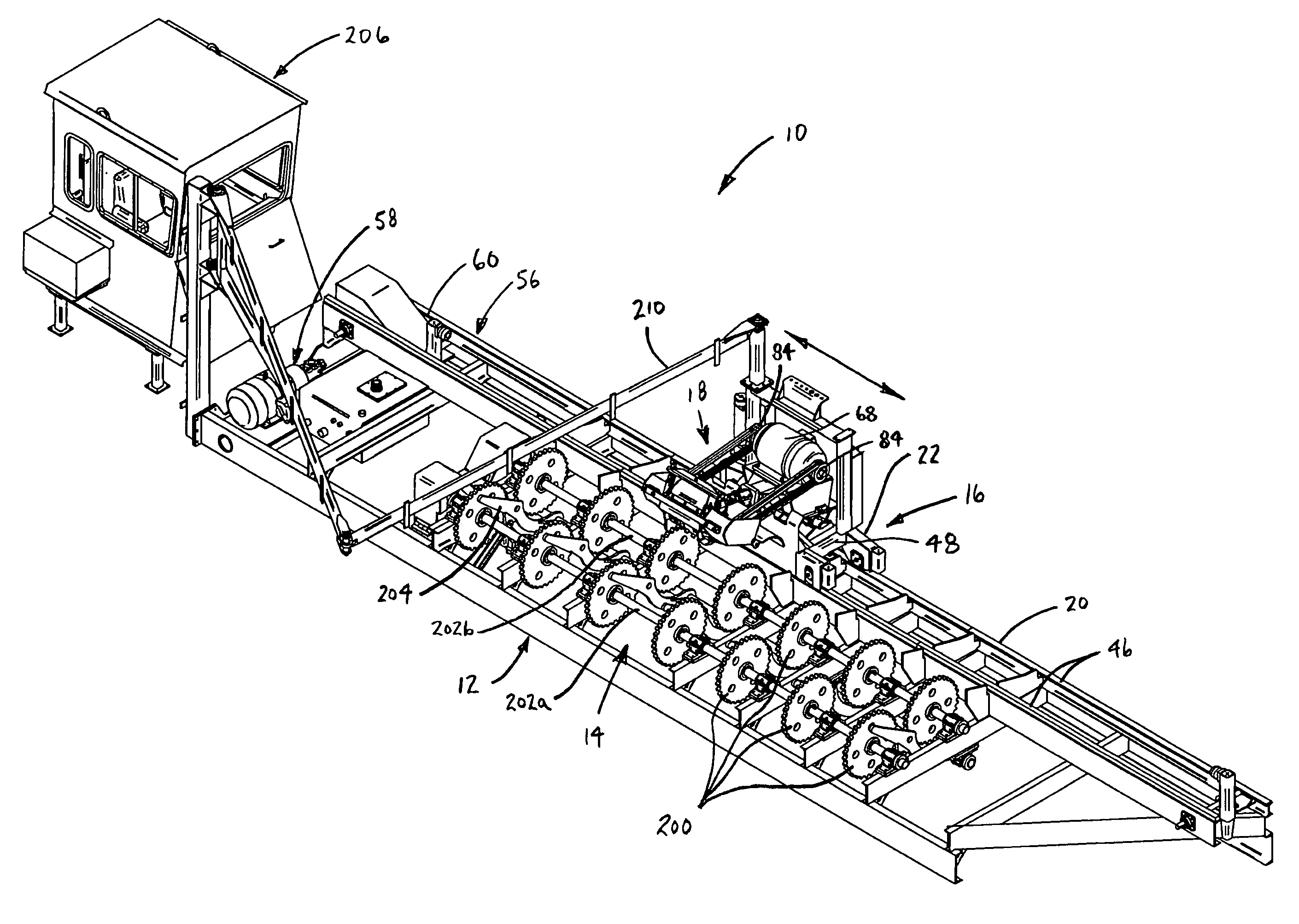
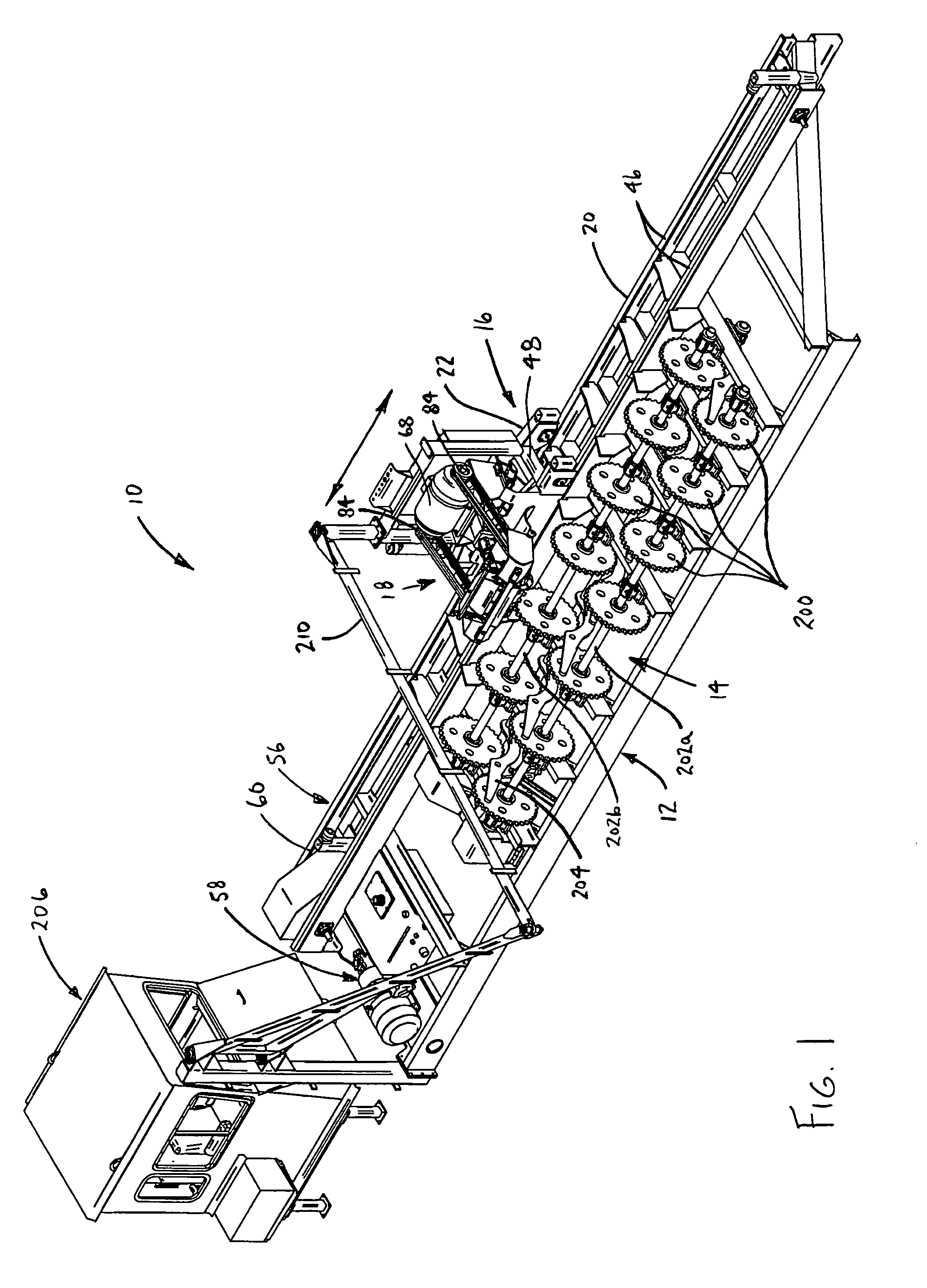
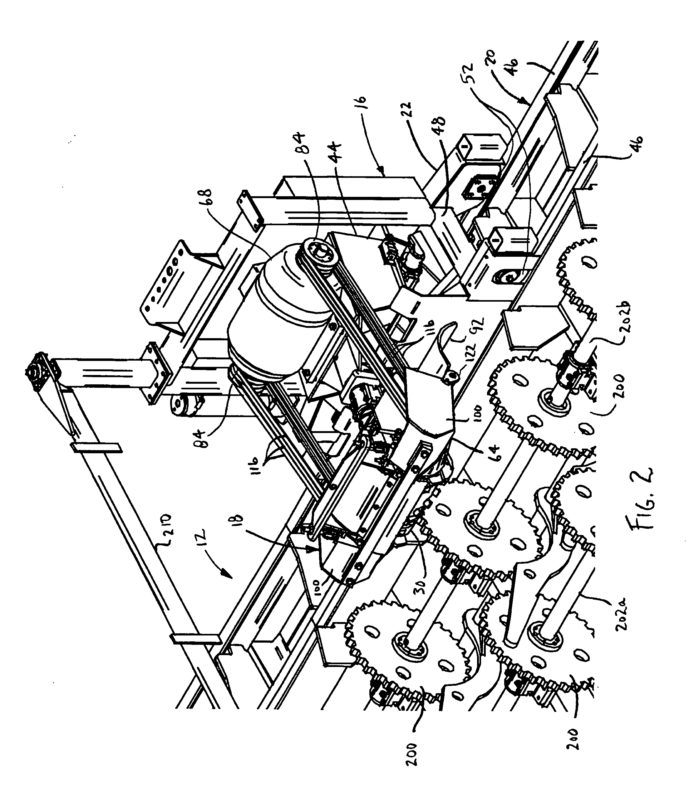
[0055]A Rosserhead debarker 10 in accordance with an embodiment of the present invention is shown in FIG. 1. The illustrated Rosserhead debarker 10 generally includes a superstructure 12, a log turning assembly 14, a carriage assembly 16, a cutter head arm 18 and an operator cab 100. The log turning assembly 14 is mounted on the superstructure 12 and provides a mechanism for turning a log to be worked. The carriage assembly 16 includes a track subassembly 20 supported on the superstructure 12 and a cutter arm carriage 22 mounted for linear movement along the track subassembly 20. The cutter head arm 18 is mounted to the carriage 22 so that it can be carried along the entire length of the log. The cutter head arm 18 includes a cutter head 30 and is pivotally mounted to the carriage 22 so that the cutter head 30 can be raised and lower onto a log (See FIG. 6, Line B). The cutter head 30 generally includes a drum 32 and a plurality of cutter teeth 34a-c. The drum 32 is rota...


PUM


Abstract

A Rosserhead debarker having a cutter head with an improved cutter teeth mounting system. The cutter head drum defines a plurality of cutter tooth slots, each having a recess at its base. The cutter teeth are fitted into the slots with the base of each tooth closely received in the corresponding recess. A portion of each tooth protrudes from the slot to receive a blade. Each cutter tooth may be secured to the drum by a fastener extending in a generally radial direction. Each cutter tooth may include a removal stud that can be used to assist in removing the tooth from the drum. The cutter head may be mounted for axial deflection and may include a pivot yoke lock for selectively locking the cutter head against axial deflection. The pivot yoke lock facilitates certain operations where axial deflection may not be desired, including those in which only one end of the cutter head is riding on the log, such as during butt reducing. The cutter head may include a manually adjustable shoe disposed on the trailing side of the cutter head. The manually adjustable shoe may be used to limit the cutting depth of the cutter head even when only the trailing end of the cutter head is riding on the log.

Description

BACKGROUND OF THE INVENTION[0001]The present invention relates to equipment for processing felled timber and more particularly to an apparatus for removing bark and other undesired material from logs.[0002]When processing felled timber for use in the production of lumber, it is typically beneficial to remove bark, knots and other undesirable material from the log. A variety of machinery has been developed and is commercially available for carrying out the debarking process. Although the removal of bark, knots and other irregularities from a log is beneficial, it is typically desirable not to remove any more material from the log than necessary. If too much material is removed, it can, among other things, have a negative impact on the lumber produced from the log. For example, cutting away even a small portion of the diameter of the log can reduce the overall volume of lumber and the size of the lumber that can be produced from the log. This can significantly reduce the revenue gener...

Claims


Application Information

Patent Timeline
Patent Type & Authority Applications(United States)
IPC IPC(8): B27L1/00B27G13/00
CPCB27L1/10B27G13/04
Inventor MCQUEEN, RICHARD L.SANDBORN, LAVERN T.
Owner MORBARK FORESTRY PROD INC
Why Eureka
Try Eureka