
Multiple Point Adjustable Depth Air Sparging Well System

a multi-point adjustable, depth-adjusting technology, applied in the direction of fluid removal, sealing/packing, borehole/well accessories, etc., can solve the problems of limited success of mechanical adjustment of air sparge wells using specialized equipment, and achieve the effect of increasing air distribution

Inactive Publication Date: 2009-10-22
THE UNITED STATES OF AMERICA AS REPRESENTED BY THE SECRETARY OF THE NAVY
View PDF2 Cites 3 Cited by
  • Summary
  • Abstract
  • Description
  • Claims
  • Application Information

AI Technical Summary

Benefits of technology

[0011]The multiple adjustable depth air sparging well system comprising the present invention provides for multiple adjustable points of air injection and a second stationary point of air injection to remove all volatile contaminants from the saturated or ground water regions of the soil subsurface being treated. The present invention permits multiple air injection points and adjustability of these injection points to significantly increase the distribution of air an air channels surrounding a single air sparge well casing.
[0016]The air compressor / blower supplies pressurized air via the flexible air supply line to a well head air supply manifold positioned at the upper end of the well casing for multiple point adjustable depth air sparging well. The manifold is pneumatically sealed using a compression fitting containing a rubber o-ring. The compression fitting prevents pressurized air from escaping into the atmosphere through the well head. In addition, the compression fitting seal serves the purpose of mechanically locking the each of the multiple flow-through packers in place at a pre-selected depths chosen by operator. This prevents vertical movement of the flow-through packers when the air sparging well system is operational.
[0017]The pressurized air traveling through each of the flow-through packers within the well casing inflates each of the flow-through packers, sealing each packer against the well casing's internal wall and preventing the injected air from flowing back up the interior of the well casing, which insures that the air flow is through the multiple injection points into the air channels formed within contaminated groundwater zone within the soil's subsurface.

Problems solved by technology

Attempts to mechanically adjust air sparge wells with specialized equipment have met with only limited success.

Method used


Image

  • Multiple Point Adjustable Depth Air Sparging Well System
  • Multiple Point Adjustable Depth Air Sparging Well System
  • Multiple Point Adjustable Depth Air Sparging Well System

Examples


Embodiment Construction

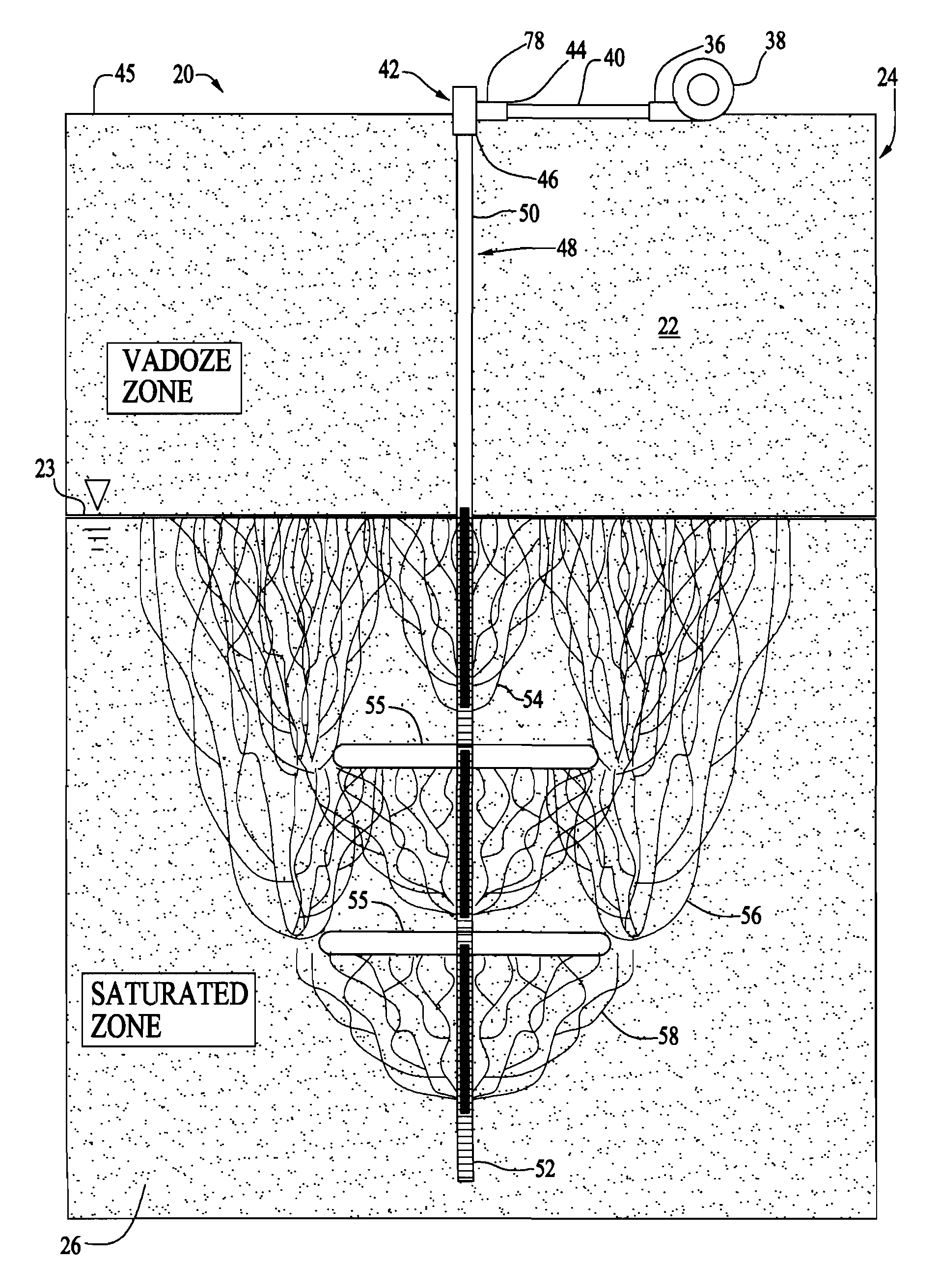
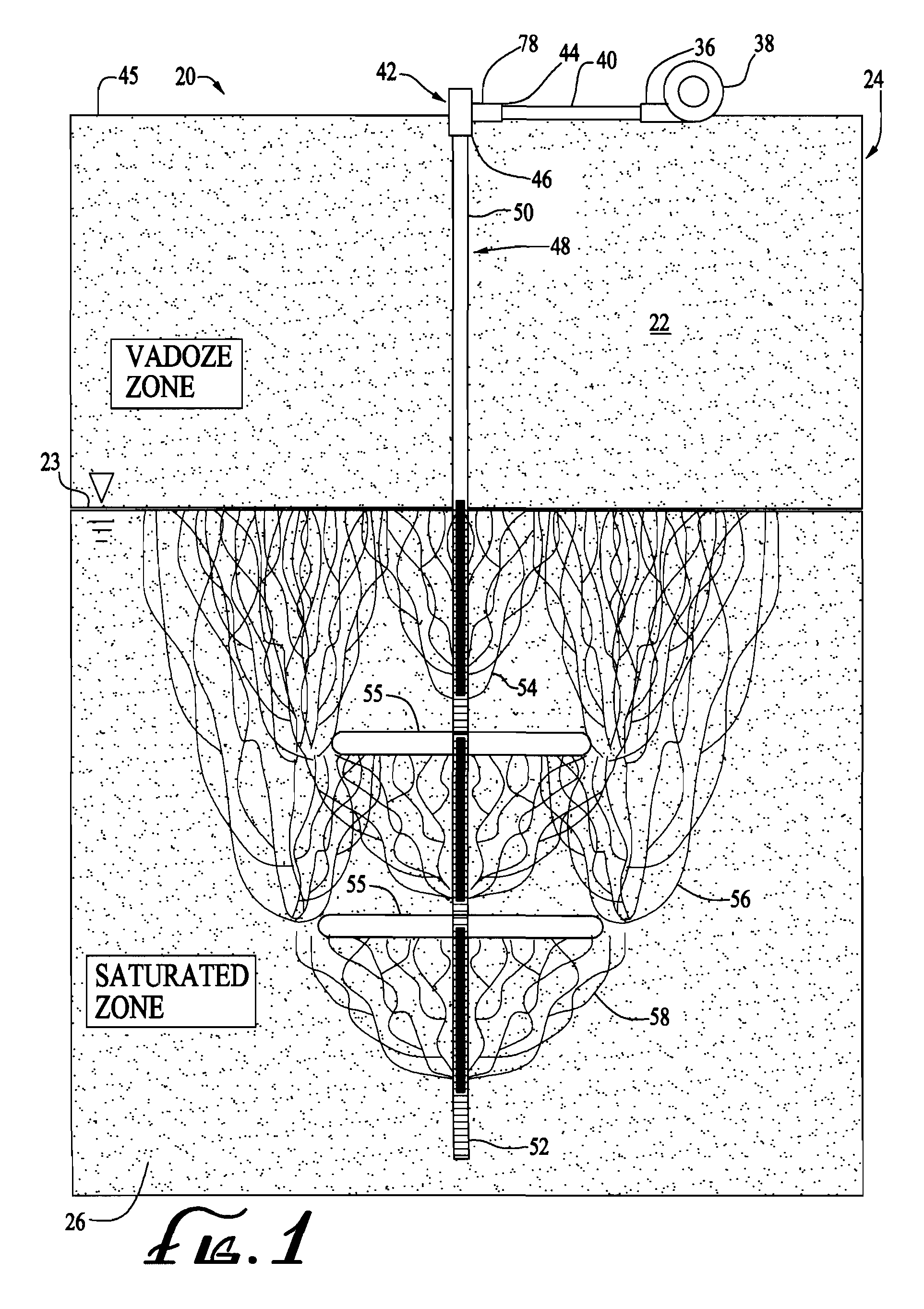
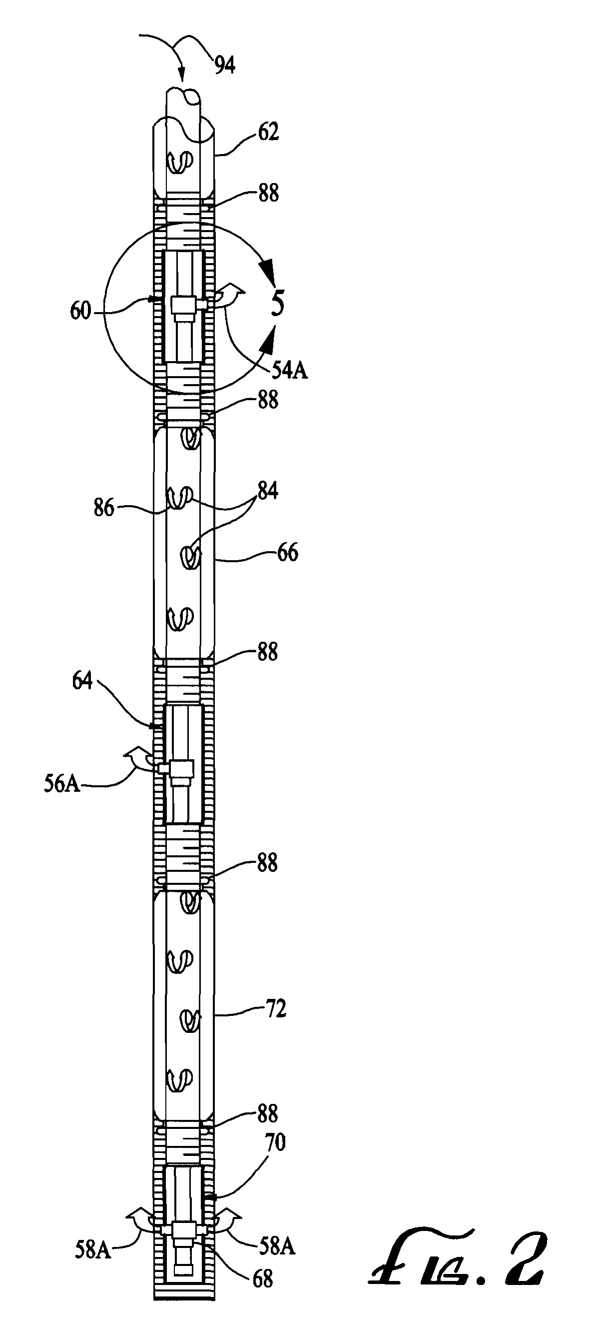
[0027]Referring to FIGS. 1 and 2, FIGS. 1 and 2 illustrate a preferred embodiment of the multiple point adjustable depth air sparging well system 20 comprising the present invention. The multiple point adjustable depth air sparging well system 20 removes volatile contaminants, such as jet fuel, solvents and industrial contaminants from the saturated or groundwater regions of the soil's subsurface. The multiple point adjustable depth air sparging well system 20 is vertically positioned in the soil 24 in the manner illustrated in FIG. 1 and passes through the vadoze zone 22 of the soil 24 into the saturated or groundwater zone 26 of the soil 24. It should be noted that the saturated zone 26 of the soil 24 is homogeneous except for the confining soil lense. Boundary line or water table 23 indicates where in the soil the boundary between vadoze zone 22 and saturated zone 26 occurs.

[0028]An air blower / air compressor 38 supplies pressurized air via an air supply line 40 to a well head air...


PUM


Abstract

An multiple point adjustable depth air sparging well system having a multiple air injection points for injecting compressed air into saturated or groundwater regions of the soil's subsurface to remove volatile contaminants from the soil's subsurface. At plurality of flow-through air sparge packer which are slidably mounted flow-through packers within the well casing of the air sparging well system allows a user to adjust the depths of the air injection points. Each packer has attached thereto a pressure regulator which provides compressed air to one of the multiple air injection points.

Description

[0001]This application is a continuation-in part of U.S. patent application Ser. No. 12 / 235,961, filed Sep. 23, 2008, which is a continuation-in-part of U.S. patent application Ser. No. 11 / 527,659, filed Sep. 21, 2006, now abandoned.BACKGROUND OF THE INVENTION[0002]1. Field of the Invention[0003]The present invention relates generally to a system for removing environmentally harmful volatile contaminants from saturated or groundwater regions of the soil subsurface. More particularly, the present invention relates to a multiple point adjustable depth air sparging system which uses injected air to remove volatile contaminants from saturated or groundwater regions of the soil's subsurface.[0004]2. Description of the Prior Art[0005]Air sparging is a relatively recent and a very innovative environmental remediation technology that uses air injected under pressure to remove environmentally harmful volatile contaminants from a contaminated groundwater zone within the soil's subsurface. Air...

Claims


Application Information

Patent Timeline
IPC IPC(8): E21B37/00
CPCB09C1/005B09C1/002
Inventor DRUCKER, ANDREW SCOTT
Owner THE UNITED STATES OF AMERICA AS REPRESENTED BY THE SECRETARY OF THE NAVY
Learn More