Regenerative shock absorber

a shock absorber and regenerative technology, applied in the field of shock absorbers, can solve the problems of increasing damping force, and achieve the effect of increasing fuel efficiency

Active Publication Date: 2009-10-22
CLEARMOTION INC
View PDF95 Cites 131 Cited by
  • Summary
  • Abstract
  • Description
  • Claims
  • Application Information

AI Technical Summary

Benefits of technology

[0009]The electric energy generated by the generator may be used by the vehicle as it is generated or stored in, for example, the vehicle's battery. It is preferre...

Problems solved by technology

The damping force provided by the motor is selected to be directly proportional to the veloc...

Method used


Image

  • Regenerative shock absorber
  • Regenerative shock absorber
  • Regenerative shock absorber

Examples


Embodiment Construction

[0019]First of all, some of the theory on which the present invention is based will be discussed. It is important to note how much energy is typically lost in the vertical motion of a car or truck so as to be able to decide whether the energy is worth harvesting. The model the inventors chose to use is a simple spring-based model in which the energy that is present in the vertical motion of a car can be observed in the compression and extension of its springs. The energy in a compressed spring is given by the equation

E=∫Fx=12kx2.

Using an experimentally determined value for k of 1.2×10⁵ N / m, we find that for a 3500 pound automobile, vertical displacements store the amounts of energy in a single spring as shown below. We note that heavy truck springs are much stiffer.

[0020]We have approximated city driving by assuming that the springs undergo vibrations of magnitude 2 cm at a frequency 3 Hz, keeping in mind that work is done both compressing and extending the spring so that energy can...


PUM


Abstract

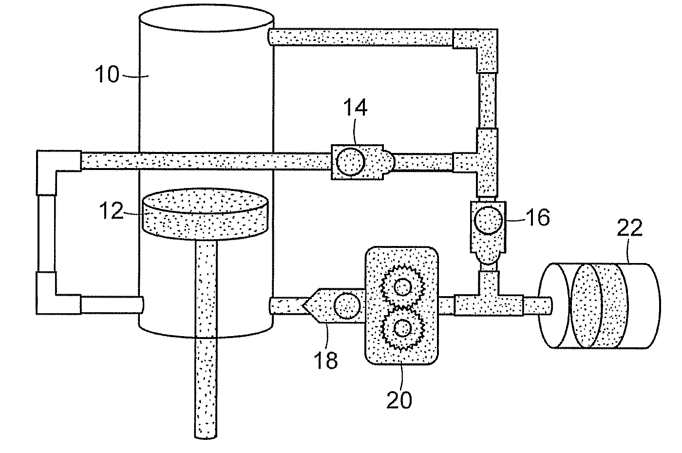
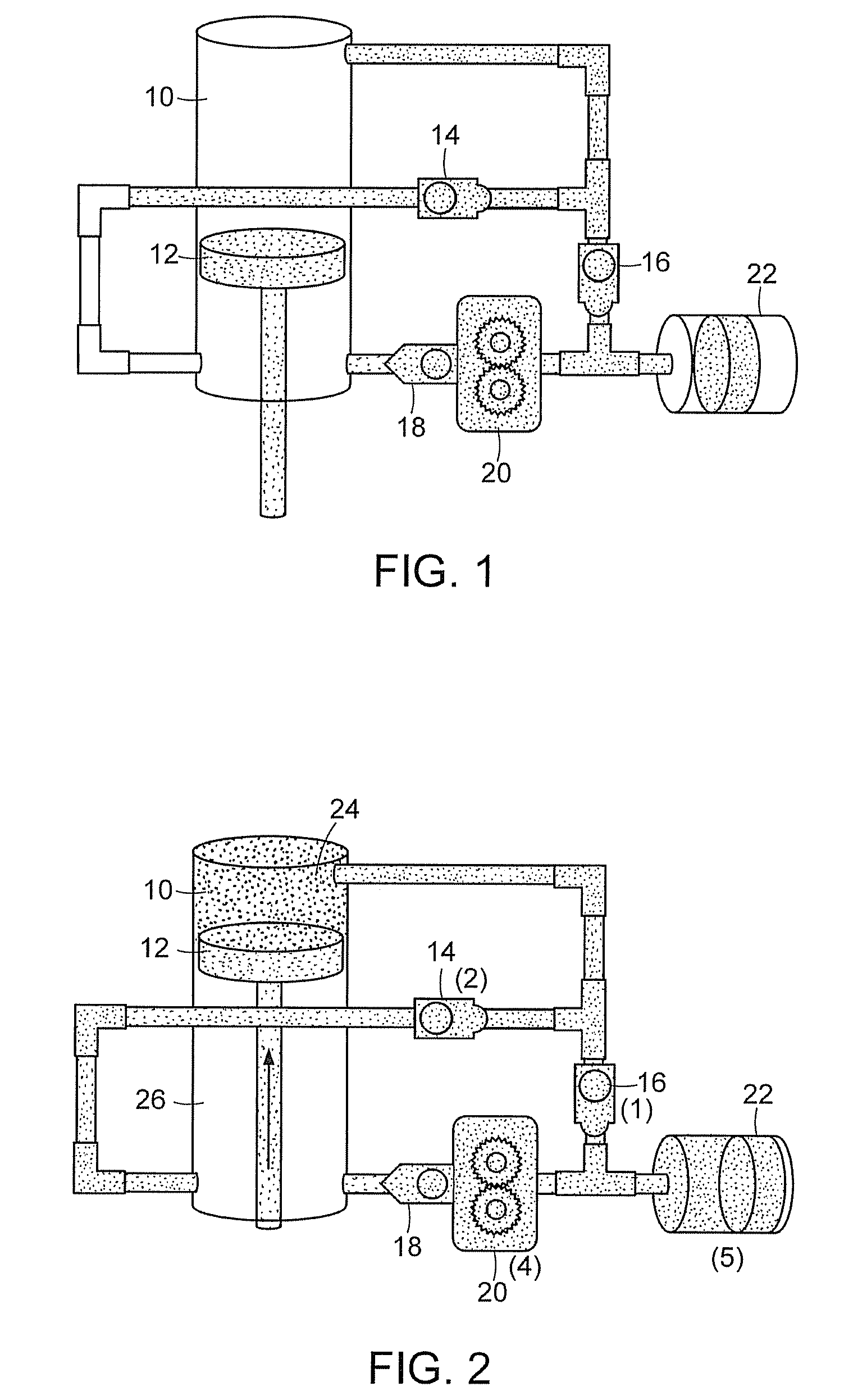
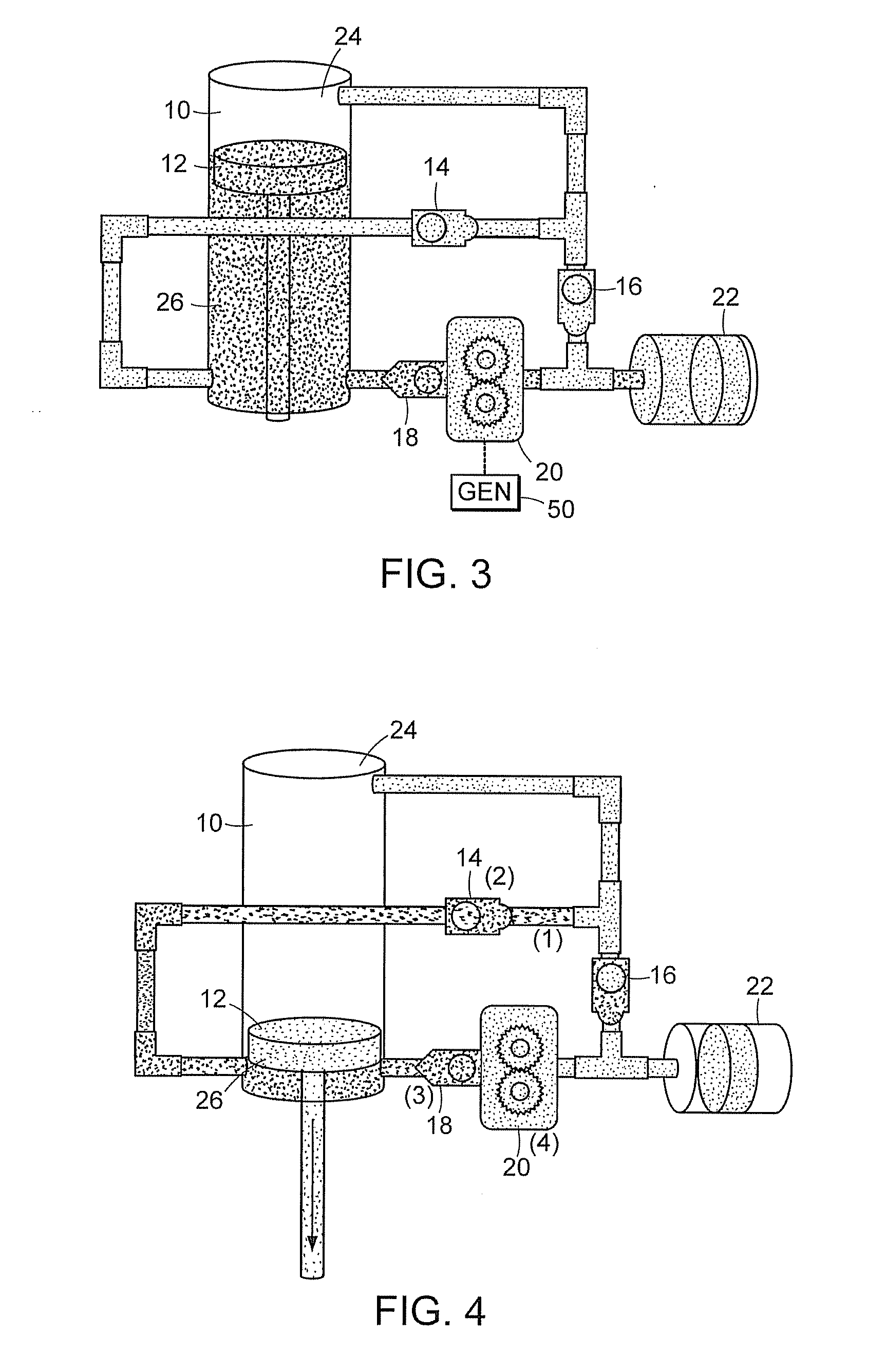
Regenerative shock absorber. A piston is disposed for reciprocating motion within a cylinder as a vehicle's suspension system deflects. Hydraulic fluid passes through an hydraulic motor to turn its shaft. The hydraulic motor shaft is connected to an electric generator to generate electricity. Flow characteristics of hydraulic circuits are selected to provide suspension system damping for appropriate wheel control.

Description

BACKGROUND OF THE INVENTION[0001]This invention relates to shock absorbers and more particularly to shock absorbers that capture energy resulting from the relative motion of a vehicle's suspension system.[0002]It is known that automobiles are inefficient, wasting over 80% of the energy stored in the fuel as heat. Thus eight of every ten gallons in the vehicle's tank don't help propel the vehicle.[0003]Automobile manufacturers have made costly strides to improve fuel economy. For example, regenerative braking is standard on many hybrid automobiles. Car makers also spend a great deal of effort to reduce wind drag so as to improve fuel economy through streamlined, low drag automobile body designs. Manufacturers also use lighter, yet more expensive, materials to reduce vehicle weight to reduce fuel consumption.[0004]Motor vehicles include a suspension system to control vertical motion of the wheel with respect to the vehicle. In addition to springs, shock absorbers are provided to provi...

Claims


Application Information

Patent Timeline
IPC IPC(8): F16F9/24
CPCB60G13/14B60K25/10B60G2300/60
Inventor AVADHANY, SHAKEELABEL, PAULTARASOV, VLADIMIRANDERSON, ZACK
Owner CLEARMOTION INC
Why Eureka
Try Eureka