Shock absorber

Inactive Publication Date: 2009-10-22
HITACHI LTD
View PDF14 Cites 24 Cited by
  • Summary
  • Abstract
  • Description
  • Claims
  • Application Information

AI Technical Summary

Benefits of technology

[0007]The present invention has been made in view of the above-described circumstances. Accordingly, an object of the present invention is to provide a shock absorber capable of preventing a sharp change in damping force to obtain smooth damping force characteristics.
[0008]The present invention provides a shock absorber including a cylinder having a fluid sealed therein, a piston slidably fitted in the cylinder, a fluid passage in which a flow of fluid is induced by sliding movement of the piston in the cylinder, and a damping force generating mechanism that generates a damping force by controlling the flow of fluid in the fluid passage. The damping force generating mechanism includes an orifice passage, an annular valve seat, a disk-shaped seat disk, a through-hole, and a disk valve. The orifice passage constantly allows the fluid to flow through the fluid passage. The valve seat is provided on a valve member through which the fluid passage extends. The seat disk is seated on

Problems solved by technology

Hei 3-163234, however, it becomes difficult to ensure the required sealing performance because of the complicated seat surface configuration, resulting in an increase in the production cost.
In addition, it becomes structurally diffi

Method used


Image

  • Shock absorber
  • Shock absorber
  • Shock absorber

Examples


Embodiment Construction

[0021]An embodiment of the present invention will be described below in detail with reference to the accompanying drawings.

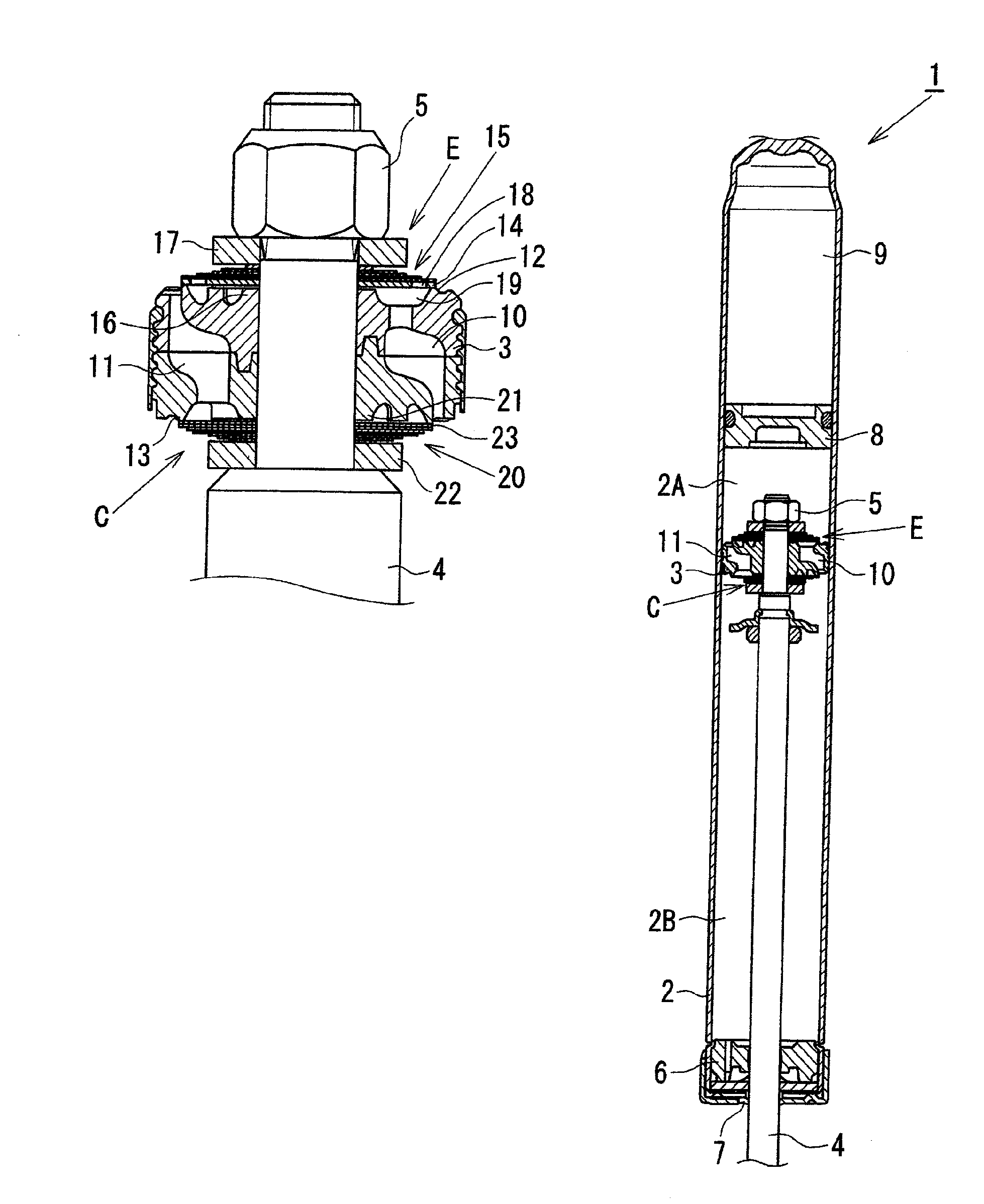
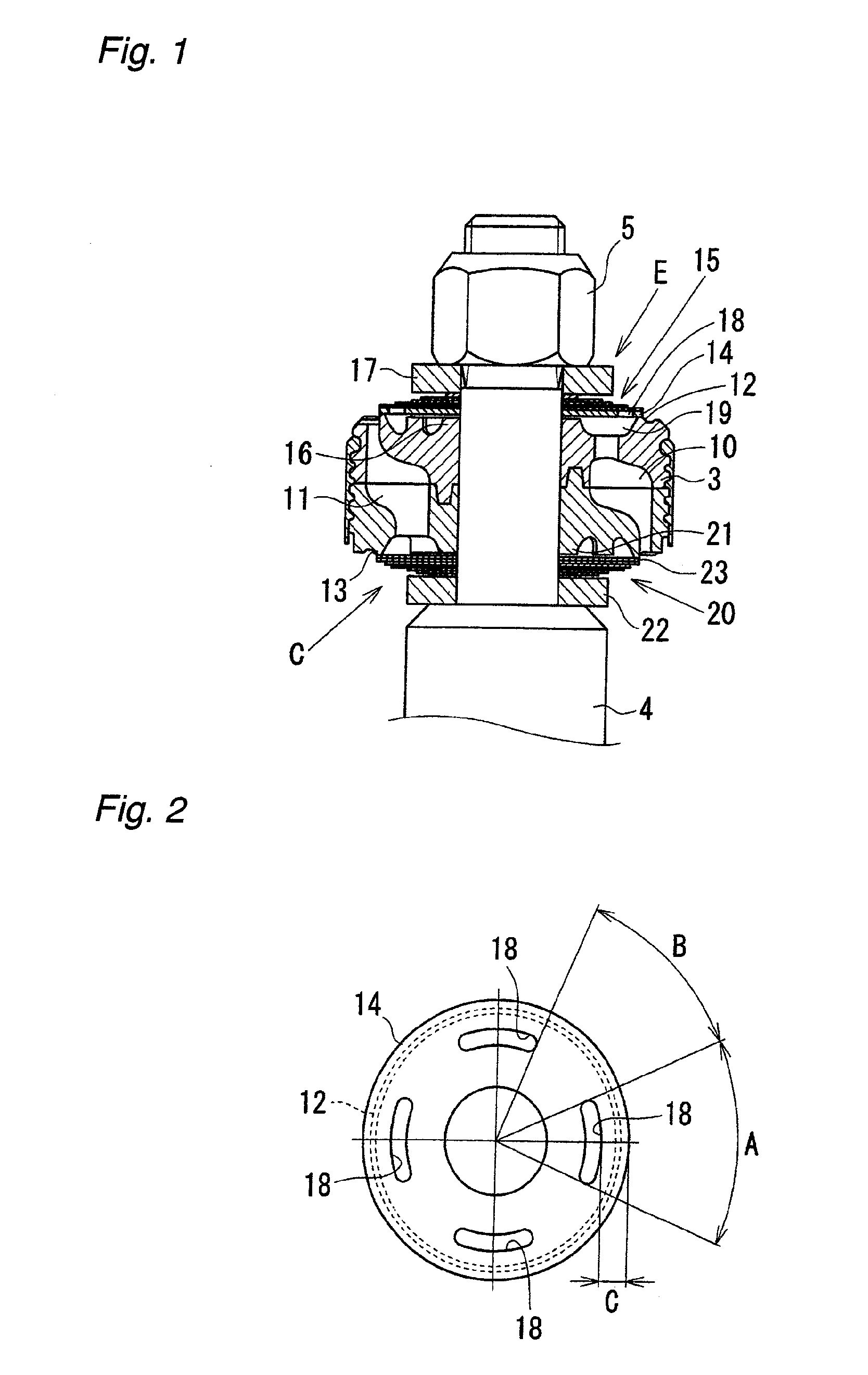
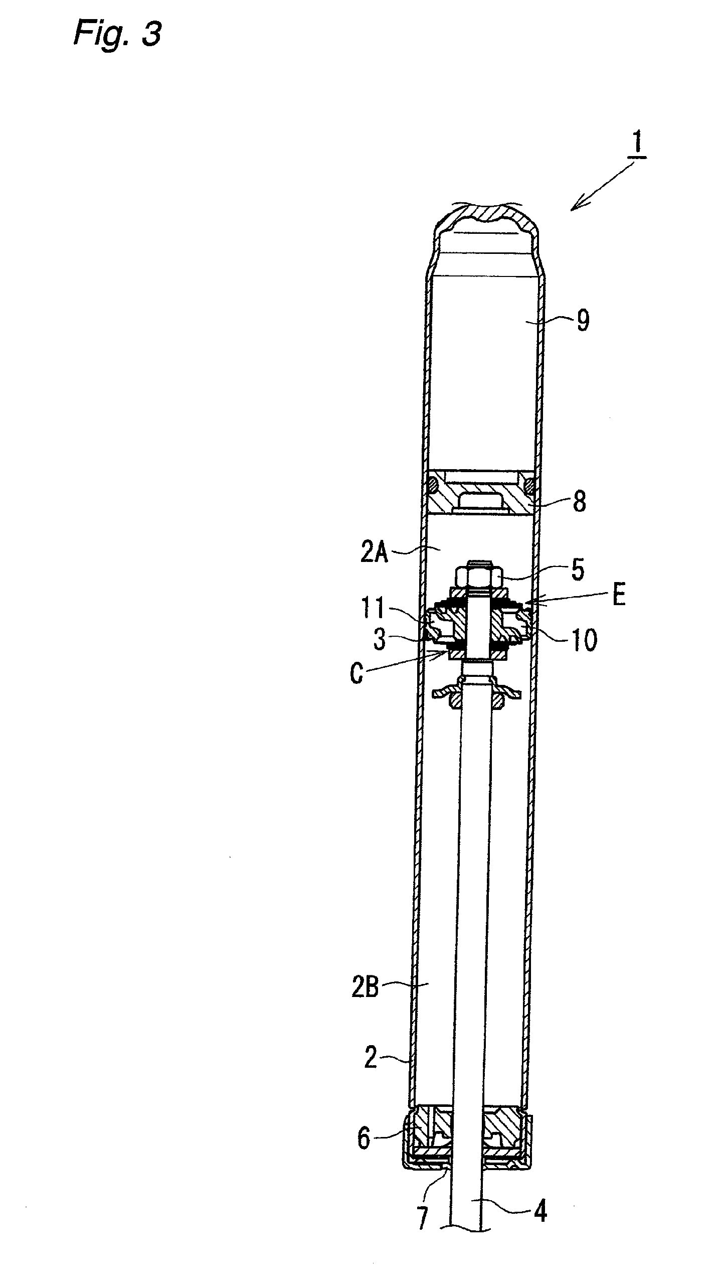
[0022]FIG. 3 is a general view showing the overall structure of a shock absorber according to this embodiment. A piston part as a main part of the shock absorber is shown in FIG. 1 in enlarged view. As shown in FIG. 3, the shock absorber 1 according to this embodiment is a single-cylinder type hydraulic shock absorber attached to a suspension system of an automobile. In the shock absorber 1, a piston 3 (valve member) is slidably fitted in a cylinder 2 having a hydraulic fluid (fluid) sealed therein. The piston 3 divides the inside of the cylinder 2 into two chambers, i.e. a cylinder upper chamber 2A and a cylinder lower chamber 2B. One end portion of a piston rod 4 extends through the piston 3 and is connected thereto with a nut 5. The other end portion of the piston rod 4 extends to the outside of the cylinder 2 through a rod guide 6 and an oil seal 7 that are ...


PUM


Abstract

A shock absorber has a seat disk seated on a valve seat of a piston. A disk valve opens and closes a slot provided in the seat disk to extend in the circumferential direction thereof. In a low piston speed region, an orifice passage generates a damping force of orifice characteristics. In an intermediate piston speed region, the disk valve opens to generate a damping force of valve characteristics. In a high piston speed region, the seat disk opens to prevent an excessive increase in damping force. The disk valve partially opens the slot relative to the circumferential direction to gradually increase the flow path area, thereby preventing a sharp change in damping force in a transitional region from the low to intermediate piston speed region.

Description

BACKGROUND OF THE INVENTION[0001]The present invention relates to shock absorbers such as hydraulic shock absorbers that utilize a fluid pressure.[0002]In general, cylinder-type hydraulic shock absorbers attached to suspension systems of automobiles or other vehicles are structured as follows. A piston connected with a piston rod is slidably fitted in a cylinder having a hydraulic fluid sealed therein. The piston is provided with a damping force generating mechanism including an orifice and a disk valve. The damping force generating mechanism generates a damping force by controlling, through the orifice and the disk valve, the flow of hydraulic fluid induced by sliding movement of the piston in the cylinder, which is caused by the extension and contraction of the piston rod.[0003]When the piston speed is low (i.e. in a low piston speed region), the orifice generates a damping force of orifice characteristics (in which the damping force is approximately proportional to the square of ...

Claims


Application Information

Patent Timeline
IPC IPC(8): F16F9/34
CPCF16F9/3484F16F9/00F16F9/32F16F9/34
Inventor HIKOSAKA, KENJI
Owner HITACHI LTD
Why Eureka
Try Eureka