Video Quality Estimation Apparatus, Method, and Program

Active Publication Date: 2009-10-22
NIPPON TELEGRAPH & TELEPHONE CORP
View PDF0 Cites 25 Cited by
  • Summary
  • Abstract
  • Description
  • Claims
  • Application Information

AI Technical Summary

Benefits of technology

[0020]According to the present invention, in estimating subjective video quality corresponding to main parameters which are input as an input coding bit rate representing the number of coding bit rates per unit time and an input frame rate representing the number of frames per unit time of an audiovisual medium, an estimation model specifying unit specifies, on the basis of the input coding bit rate (input frame rate), an estimation model representing the relationship between subjective video quality and the frame rate (coding bit rate) of the audiovisual medium. Subjective video quality corresponding to the input frame rate (input coding bit rate) is estimated by using the specified estimation model.
[0021]It is therefore possible to obtai

Problems solved by technology

On the other hand, a best-effort network such as the Internet used for the audiovisual communication services does not always guarantee the communication quality.
Additionally, encoding by an application adds encoding distortions to the video image, which are perceptible as degradation in subjective

Method used


Image

  • Video Quality Estimation Apparatus, Method, and Program
  • Video Quality Estimation Apparatus, Method, and Program
  • Video Quality Estimation Apparatus, Method, and Program

Examples


first embodiment

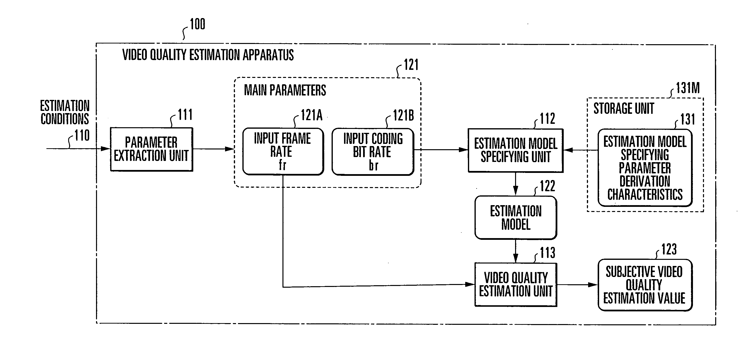
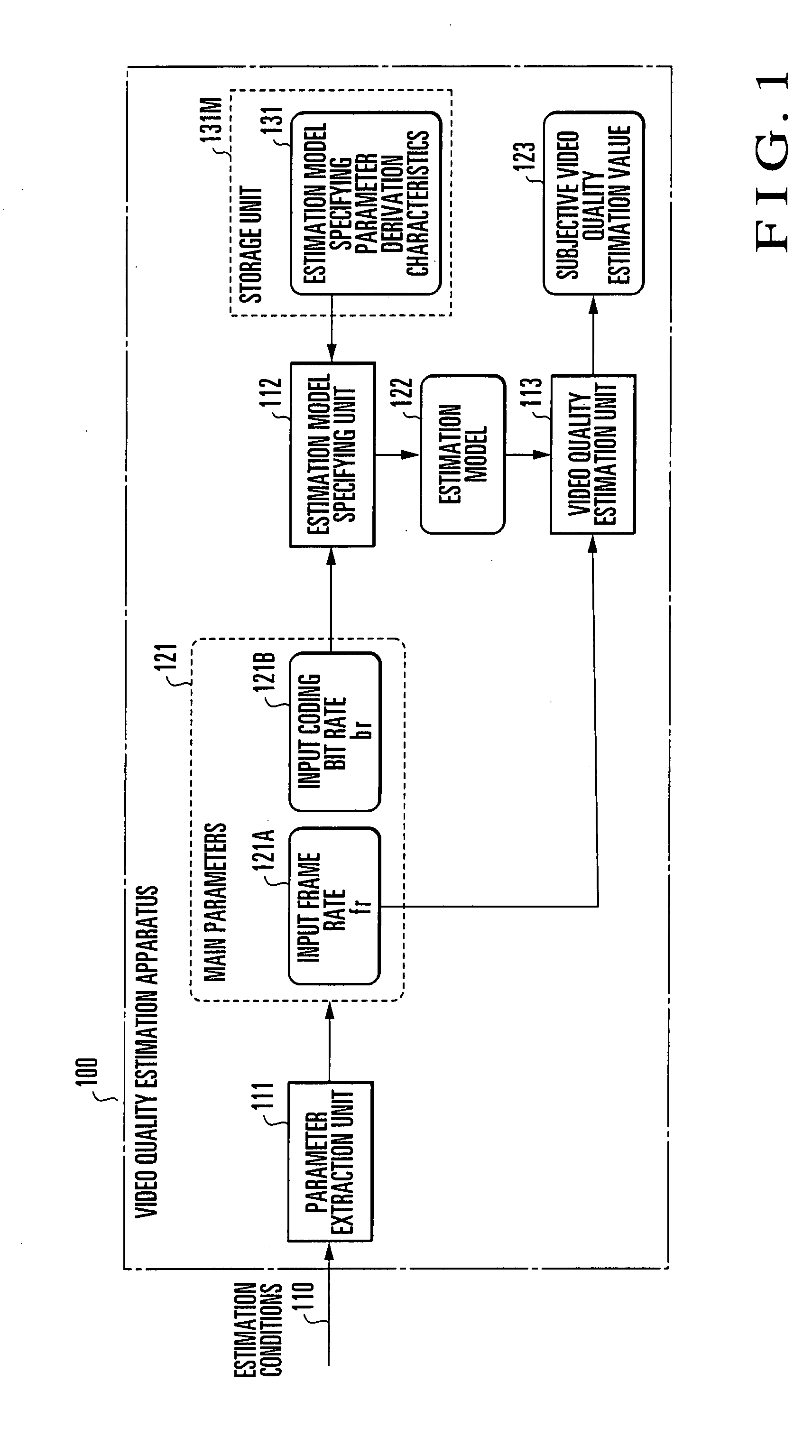
[0057]A video quality estimation apparatus according to the first embodiment of the present invention will be described first with reference to FIG. 1. FIG. 1 is a block diagram showing the arrangement of the video quality estimation apparatus according to the first embodiment of the present invention.

[0058]A video quality estimation apparatus 100 is formed from an information processing apparatus such as a computer that calculates input information. In audiovisual communication for transmitting an audiovisual medium encoded into a plurality of frames to an arbitrary terminal via a communication network, the video quality estimation apparatus 100 inputs estimation conditions about the audiovisual medium and calculates, by using a predetermined estimation model, the estimation value of subjective video quality a viewer actually senses from the audiovisual medium reproduced on the terminal.

[0059]In this embodiment, in estimating subjective video quality corresponding to main parameter...

second embodiment

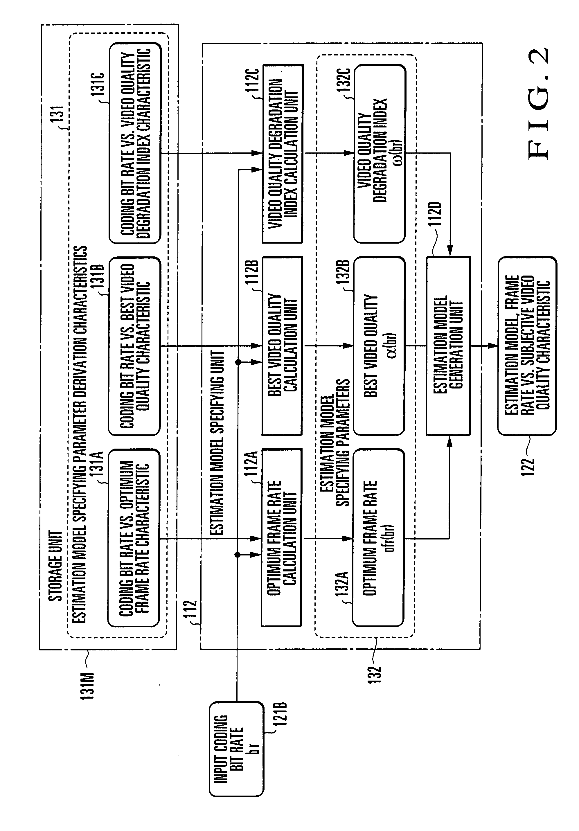
[0114]A video quality estimation apparatus according to the second embodiment of the present invention will be described next with reference to FIGS. 11 and 12. FIG. 11 is a block diagram showing the arrangement of a video quality estimation apparatus according to the second embodiment of the present invention. The same reference numerals as in FIG. 1 described above denote the same or similar parts in FIG. 11. FIG. 12 is a block diagram showing the arrangement of the estimation model specifying unit of the video quality estimation apparatus according to the second embodiment of the present invention. The same reference numerals as in FIG. 2 described above denote the same or similar parts in FIG. 12.

[0115]The first embodiment has exemplified a case in which the estimation model specifying parameters 132 corresponding to an input coding bit rate are derived by referring to the estimation model specifying parameter derivation characteristics 131 prepared in advance. In the second emb...

third embodiment

[0146]A video quality estimation apparatus according to the third embodiment of the present invention will be described first with reference to FIG. 19. FIG. 19 is a block diagram showing the arrangement of the video quality estimation apparatus according to the third embodiment of the present invention.

[0147]A video quality estimation apparatus 200 is formed from an information processing apparatus such as a computer that calculates input information. In audiovisual communication for transmitting an audiovisual medium encoded into a plurality of frames to an arbitrary terminal via a communication network, the video quality estimation apparatus 200 inputs estimation conditions about the audiovisual medium and calculates, by using a predetermined estimation model, the estimation value of subjective video quality a viewer actually senses from the audiovisual medium reproduced on the terminal.

[0148]In this embodiment, in estimating subjective video quality corresponding to main paramet...


PUM


Abstract

In estimating subjective video quality corresponding to main parameters (121/221) which are input as an input coding bit rate (121B/221B) representing the number of coding bit rates per unit time and an input frame rate (121A/221A) representing the number of frames per unit time of an audiovisual medium, an estimation model specifying unit specifies, on the basis of the input coding bit rate (121B/input frame rate (221A)), an estimation model (122/222) representing the relationship between subjective video quality and the frame rate (/coding bit rate) of the audiovisual medium. Subjective video quality corresponding to the input frame rate (121A/input coding bit rate 221B) is estimated by using the specified estimation model (122/222) and output as an estimation value (123/223).

Description

TECHNICAL FIELD[0001]The present invention relates to an audiovisual communication technique and, more particularly, to a video quality estimation technique of estimating subjective video quality a viewer actually senses when a terminal receives and reproduces an audiovisual medium encoded into a plurality of frames.BACKGROUND ART[0002]Advance in high-speed and broadband Internet access networks is raising expectations for spread of audiovisual communication services which transfer audiovisual media containing video and audio data between terminals or server terminals via the Internet.[0003]Audiovisual communication services of this type use encoding communication to improve the audiovisual medium transfer efficiency, in which an audiovisual medium is encoded into a plurality of frames and transferred using intra-image or inter-frame autocorrelation of the audiovisual medium or human visual characteristic.[0004]On the other hand, a best-effort network such as the Internet used for t...

Claims


Application Information

Patent Timeline
IPC IPC(8): H04N17/00
CPCH04N17/004
Inventor YAMAGISHI, KAZUHISAHAYASHI, TAKANORI
Owner NIPPON TELEGRAPH & TELEPHONE CORP
Why Eureka
Try Eureka