

Telephoto lens system
- Summary
- Abstract
- Description
- Claims
- Application Information
AI Technical Summary
Benefits of technology
Problems solved by technology
Method used
Image

Examples
embodiment 1
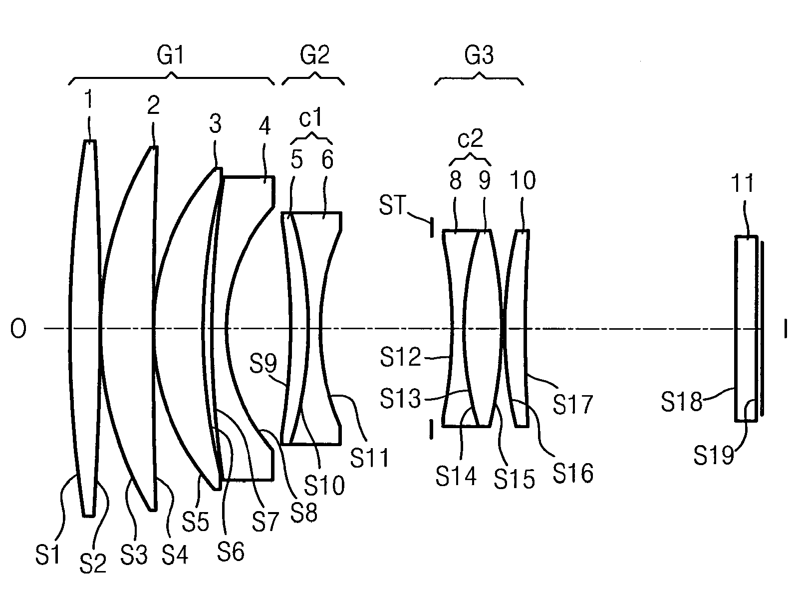
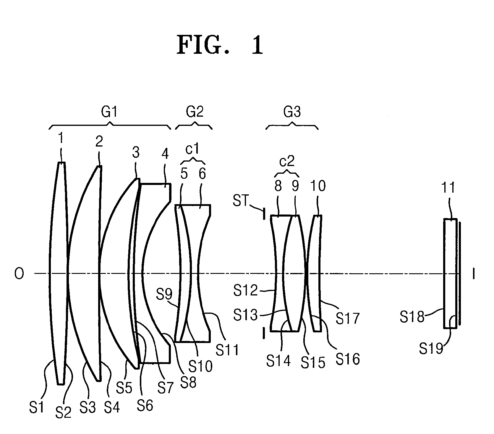
[0043]FIG. 1 is a cross-sectional view of a lens system according to an embodiment of the present invention. In FIG. 1, the lens system further includes a filter 11. Design data for the lens system of FIG. 1 is shown below.
f = 84.95 Fno = 1.44Lens surfaceRDNdVdS1194.3285.1421.6180063.4S2−503.4310.100S357.2788.9761.4970081.6S4590.4190.100S539.1228.4081.7291654.7S6108.0771.520S7166.2622.5001.6889331.2S830.27010.960S9−118.0063.0501.8466623.8S10−61.1421.8001.5407247.2S1139.85919.349S12ST3.180S13−98.4072.0001.6989530.1S1450.3956.6831.8042046.5S15−67.5630.200S1657.5453.7261.8042046.5S17379.25335.864S18Infinity3.7001.5168064.2S19Infinity0.733Magnification0.0000.020.130D(8)10.96012.92824.394D(11)19.34917.3785.915B.F.0.7330.7330.733
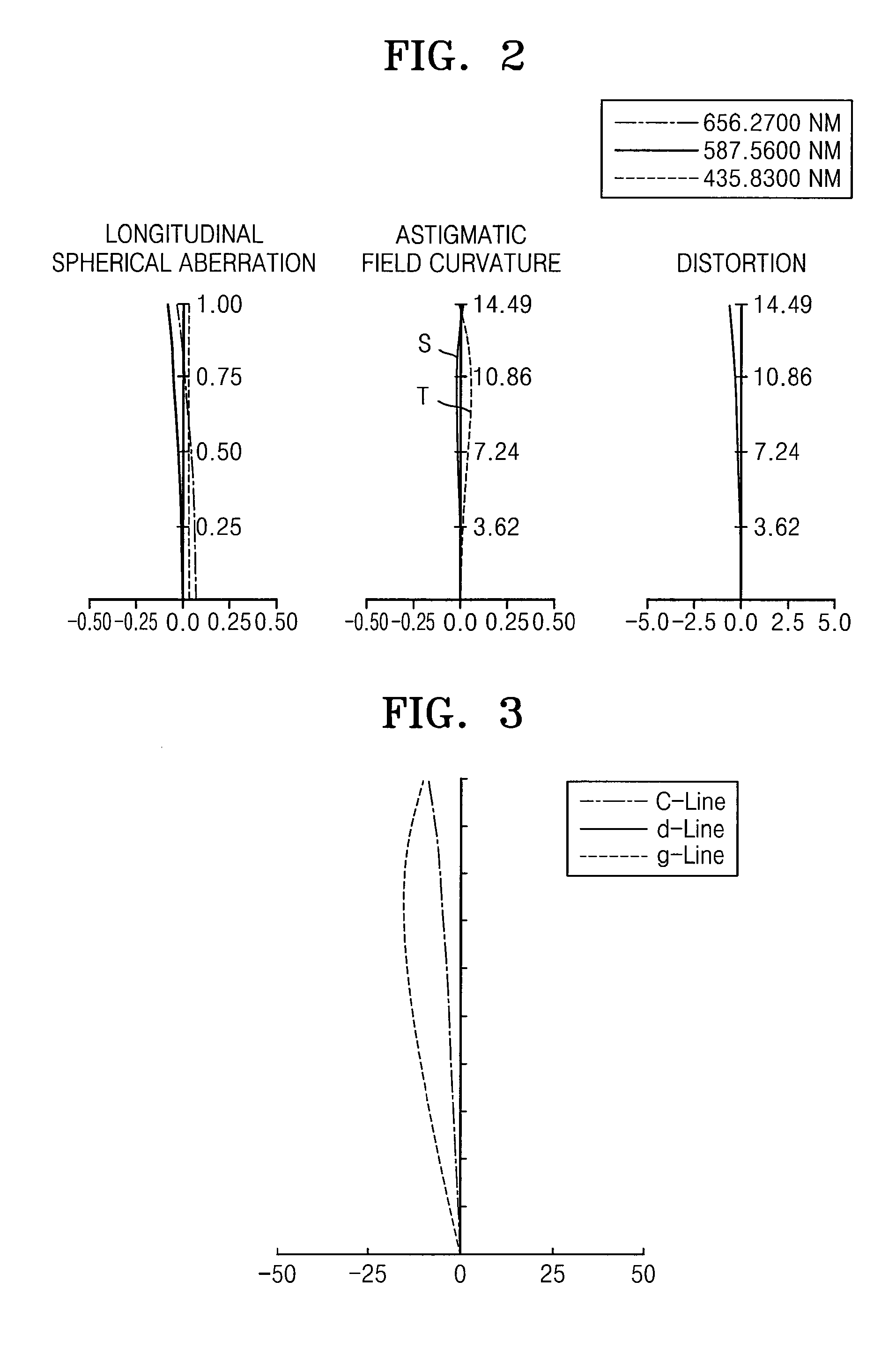
[0044]FIG. 2 illustrates the spherical aberration, astigmatic field curvature, and distortion of the lens system of FIG. 1. The astigmatic field curvature is indicated by a tangential field curvature T and a sagittal field curvature S. FIG. 3 illustrates the later...
embodiment 2
[0045]FIG. 4 is a cross-sectional view of a lens system according to another embodiment of the present invention. Design data for the lens system of FIG. 4 is shown below.
f = 84.98 Fno = 1.44Lens surfaceRDNdVdS167.99210.0101.6180063.4S2−644.6610.100S344.2937.6121.7725049.6S4107.0112.811S5423.6564.4021.6727032.2S631.6912.365S739.5497.8791.4970081.6S8−1892.4832.886S9−169.5863.8161.8466623.8S10−54.9351.8001.6056243.7S1129.22413.654S12ST5.246S13−32.9202.0001.6889331.2S1488.8686.8501.8042046.5S15−40.7460.100S1676.0634.1281.8042046.5S17−172.86435.864S18Infinity3.7001.5168064.2S19Infinity0.726Magnification0.0000.0200.124D(8)2.8863.9489.713D(11)13.65412.5926.827B.F.0.7260.7260.726
[0046]FIGS. 5 and 6 illustrate the spherical aberration, astigmatic field curvature, and distortion, and lateral chromatic aberration of the lens system of FIG. 4.
embodiment 3
[0047]FIG. 7 is a cross-sectional view of a lens system according to another embodiment of the present invention. Design data for the lens system of FIG. 7 is shown below.
f = 84.11 Fno = 1.44Lens surfaceRDNdVdS174.1339.1701.6180063.4S2−717.7580.100S341.9469.8901.8042046.5S4122.4181.270S5232.6382.5001.6989530.1S630.2702.060S737.1787.9101.4970081.6S8231.0524.008S9−372.9454.3601.8466623.8S10−53.2001.8001.7440044.9S1130.33713.552S12ST4.510S13−42.9442.5701.6989530.1S1451.6997.7401.8042046.5S15−43.1400.100S1656.7454.0401.8042046.5S171000.00036.970S18Infinity2.5001.5168064.2S19Infinity0.528Magnification0.0000.0200.129D(8)4.0085.00410.603D(11)13.55212.5576.957B.F.0.5280.5280.528
[0048]FIGS. 8 and 9 illustrate the spherical aberration, astigmatic curvature, and distortion, and lateral chromatic aberration of the lens system of FIG. 7.
PUM
 Abstract
Description
Claims
Application Information