Belt driving device and image forming apparatus

a driving device and belt technology, applied in the direction of electrographic process apparatus, instruments, optics, etc., can solve the problems of affecting the accuracy of the reference timing determined during the rotation, the thickness of the belt member that has been manufactured by centrifugal molding technique is likely to be inconsistent, and the method incurs increased costs, so as to prevent color shift and increase costs

Active Publication Date: 2009-10-22
RICOH KK
View PDF4 Cites 19 Cited by
  • Summary
  • Abstract
  • Description
  • Claims
  • Application Information

AI Technical Summary

Benefits of technology

[0017]According to one embodiment of the present invention, a belt driving device and an image forming apparatus are provided, which are capable of preventing color shift caused by errors in determining the reference timing when an image carrier or an opposing member contacts / separates from a belt member, without the need for a home position sensor that incurs increased cost.

Problems solved by technology

A belt member that has been manufactured by a centrifugal molding technique is likely to have an inconsistent thickness due to the eccentricity of the die, in which the thickest portion and the thinnest portion may have a phase difference of 180° within one rotation of the belt.
However, this method incurs increased costs for applying a home position mark on the belt member and providing a home position sensor.
However, with a belt driving device having such a configuration, when the image carrier (for example, a photoconductor) and the belt member are separated from each other, the reference timing determined during this rotation may be significantly erroneous.
Assuming that the image forming apparatus with such a configuration uses the above-described virtual home position, the following problems arise.
During these operations, when the Y, M, and C photoconductors come in contact with the belt member, the load on the driving motor may rapidly increase, which may instantaneously significantly decrease the moving speed of the belt member.
As a result, the waveform of the speed variation pattern may become considerably irregular.
Such an erroneous detection causes a considerable error in determining the reference timing.
In this case, the load on the driving motor may rapidly decrease, which may instantaneously significantly increase the moving speed of the belt member.
Such an instantaneous increase in the moving speed may cause a considerable error in determining the reference timing.
When there is a considerable error in determining the reference timing of the belt member, the moving speed of the belt member cannot be properly stabilized in the subsequent rotation, which leads to considerable color shift.
The same problems arise when making any other opposing member facing the belt member come in contact with / separate from the belt member.
For example, a belt cleaning device for cleaning off residual toner remaining on the surface of the belt member after the transfer process, or an opposing member such as a transfer member for contacting the surface of the belt member to form a transfer nip, may be configured to come in contact with / separate from the belt member, which leads to the same problems as described above.

Method used


Image

  • Belt driving device and image forming apparatus
  • Belt driving device and image forming apparatus
  • Belt driving device and image forming apparatus

Examples


Embodiment Construction

[0027]A description is given, with reference to the accompanying drawings, of embodiments of the present invention.

[0028]An electrophotographic printer (hereinafter, simply referred to as “printer”) is taken as an example of an image forming apparatus to which an embodiment of the present invention is applied.

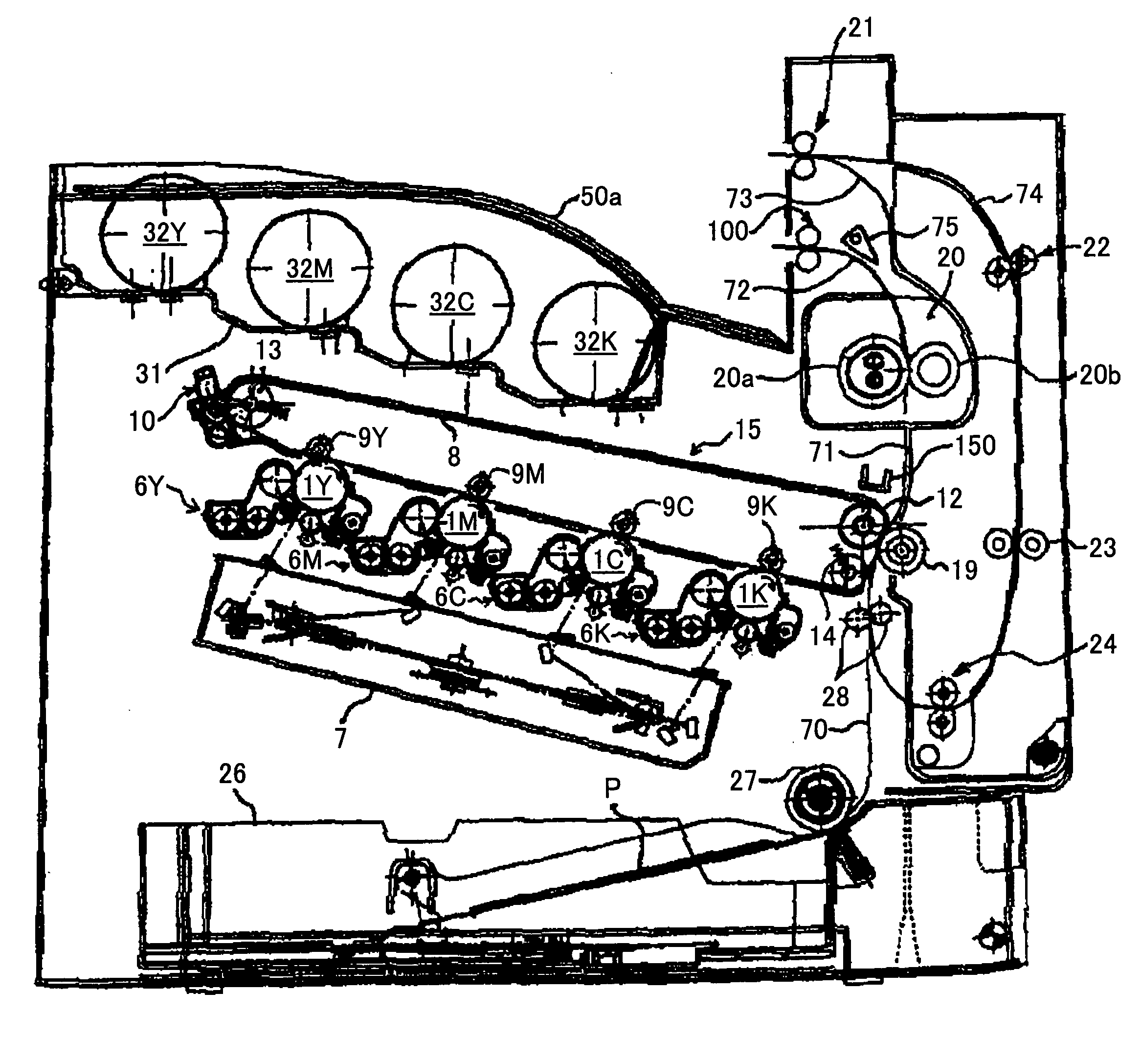
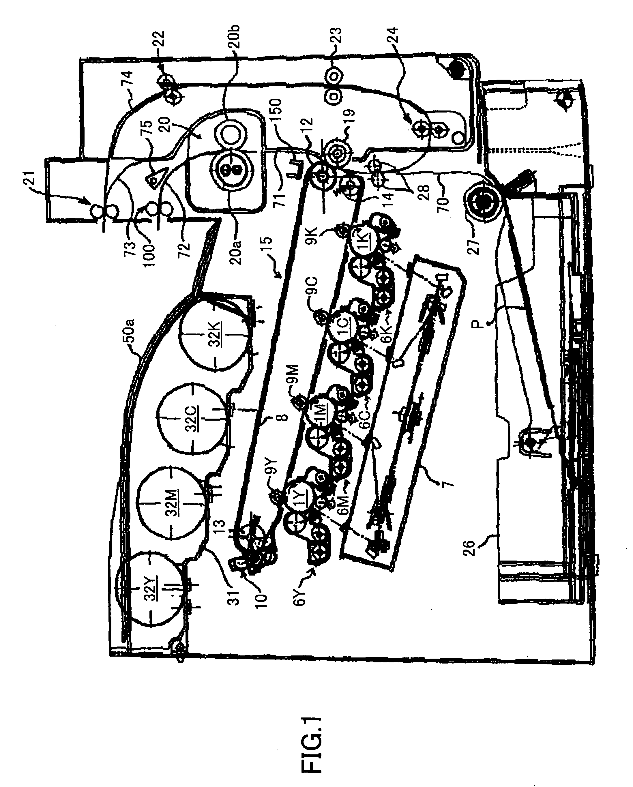
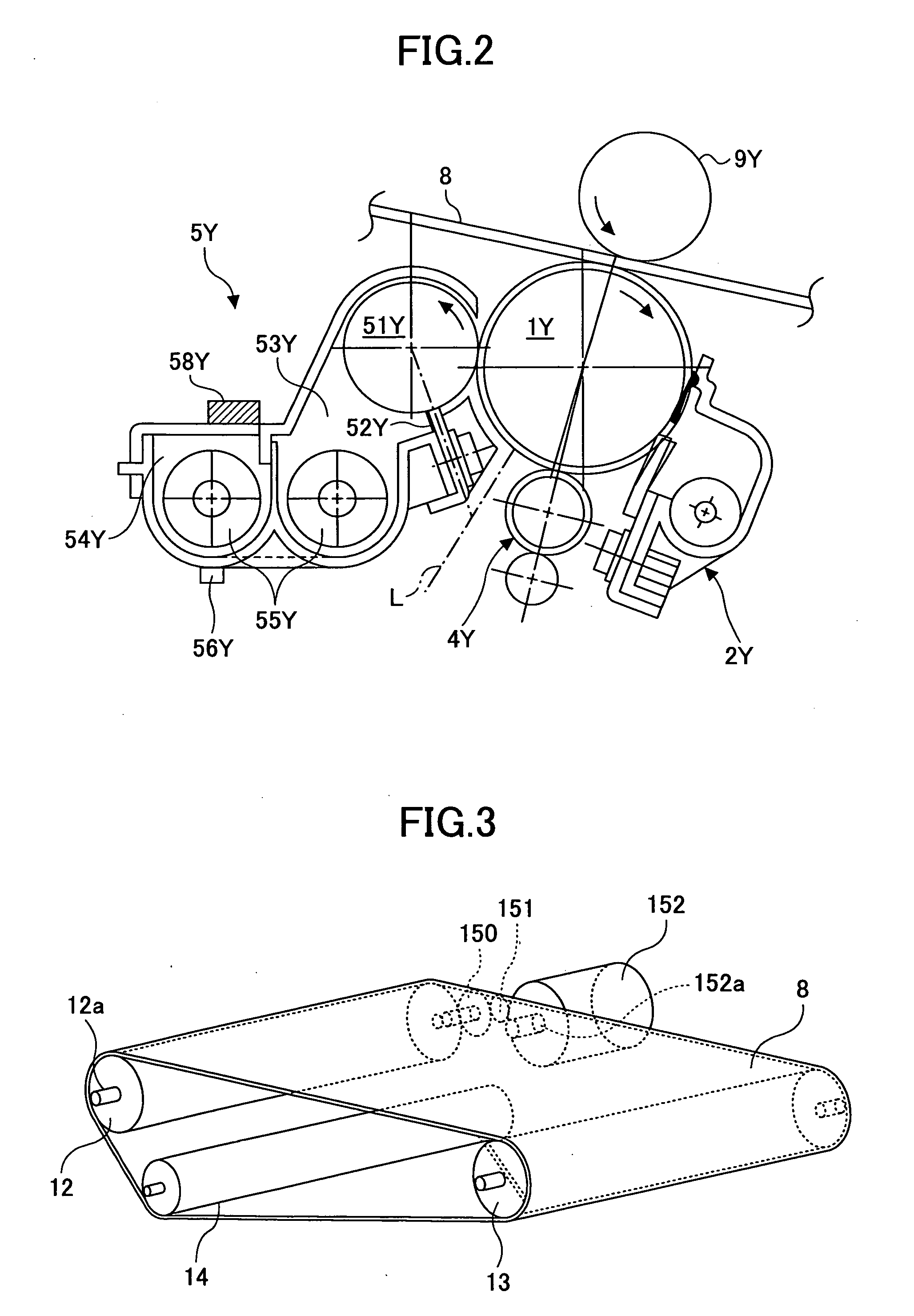
[0029]A description is given of the basic configuration of the printer. FIG. 1 is a schematic diagram of the printer. As, the printer includes four process units 6Y, 6M, 6C, and 6K for forming toner images of yellow, magenta, cyan, and black (hereinafter, “Y, M, C, and K”). These process units 6Y, 6M, 6C, and 6K use toner Y, M, C, and K of different colors as the image forming substance, but otherwise have the same configuration. Each process unit is replaced with a new one when its operating life comes to an end. As shown in FIG. 2, the process unit 6Y for generating Y toner images, which is taken as an example, includes a drum type photoconductor 1Y acting as a latent image c...


PUM


Abstract

In an image forming apparatus, during a rotation of an intermediate transfer belt performed after a contact-state-changing rotation in which the number of photoconductors contacting the intermediate transfer belt has changed, a control unit of a belt driving device controls the driving speed of a belt driving motor based on a period of the intermediate transfer belt determined in the rotation immediately before the contact-state-changing rotation instead of a period determined in the contact-state-changing rotation.

Description

BACKGROUND OF THE INVENTION[0001]1. Field of the Invention[0002]The present invention relates to a belt driving device for controlling the driving speed of a driving source of a driving / rotating body for endlessly moving a belt member by detecting the speed variation pattern during one rotation of the belt member. Furthermore, the present invention relates to an image forming apparatus such as a copier, a fax machine, and a printer, that is provided with such a belt driving device.[0003]2. Description of the Related Art[0004]Conventionally, such an image forming apparatus is known, as described in patent document 1. The image forming apparatus includes a transfer unit for endlessly moving an endless intermediate transfer belt acting as a belt member, which is stretched around a driving roller and plural subordinate rollers. The image forming apparatus includes four separate photoconductors corresponding to yellow, magenta, cyan, and black (hereinafter, “Y, M, C, and K”) as image car...

Claims


Application Information

Patent Timeline
Patent Type & Authority Applications(United States)
IPC IPC(8): G03G15/00
CPCG03G15/161G03G2215/0132G03G15/1615G03G2215/1623G03G2215/1661G03G2215/0193
Inventor MURATA, TAKUYAKOBAYASHI, KAZUHIKOMATSUDA, YUJIUEDA, YUICHIROMATSUDA, HIROMICHIANDOH, TOSHIYUKIEBARA, JOHMIURA, YOHEIUEHARA, TAKUYA
Owner RICOH KK
Why Eureka
Try Eureka