Inverter device

a technology of inverter and phase current, which is applied in the direction of motor/generator/converter stopper, dynamo-electric converter control, piston pump, etc., can solve the problems of unsatisfactory noise and vibration, and achieve high frequency, high reliability of operation, and suppression of noise and vibration

Active Publication Date: 2009-10-22
PANASONIC CORP
View PDF1 Cites 44 Cited by
  • Summary
  • Abstract
  • Description
  • Claims
  • Application Information

AI Technical Summary

Benefits of technology

[0016]With the structure above, the inverter circuit of the present invention prevents cyclic occurrence of ripple current having the same polarity and therefore suppresses noise and vibration having high frequencies. The noise and vibration caused by the ripple current in the first correction is cancelled out by the noise and vibration caused by the ripple current in the second correction because of the opposite polarity of the ripple current. Besides, the ripple current, which alternately changes polarity from positive to negative, produces low and smooth frequencies. In this way, employing a single current-sensor allows the inverter device to have a compact and lightweight structure, at the same time, the structure offers highly reliable operation with low noise and vibration.

Problems solved by technology

The ripple current as an electromagnetic force affects the stator winding of the motor, mechanical components and the housing, inviting undesirable noise and vibration.

Method used


Image

  • Inverter device
  • Inverter device
  • Inverter device

Examples


first exemplary embodiment

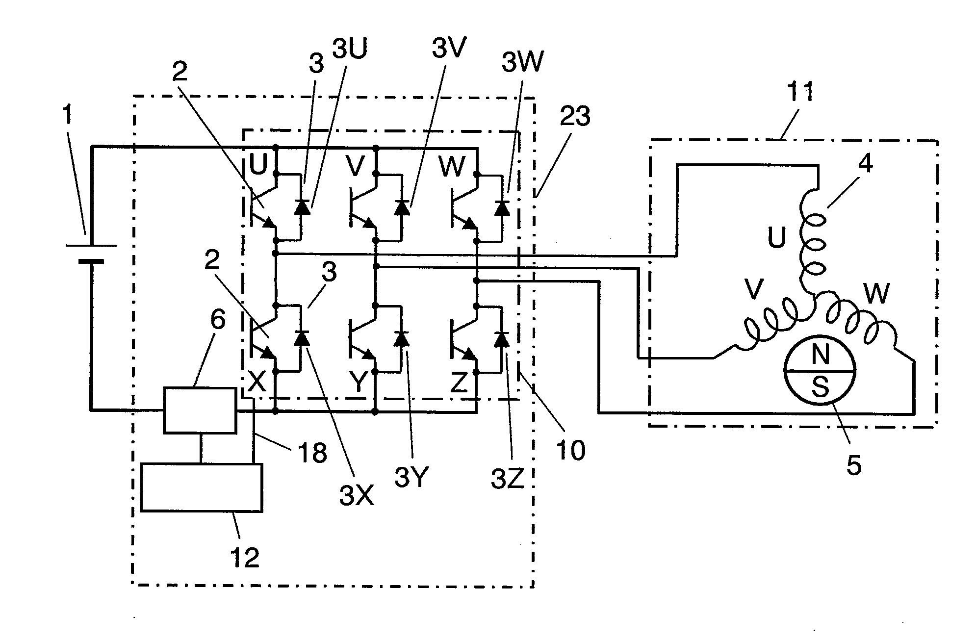
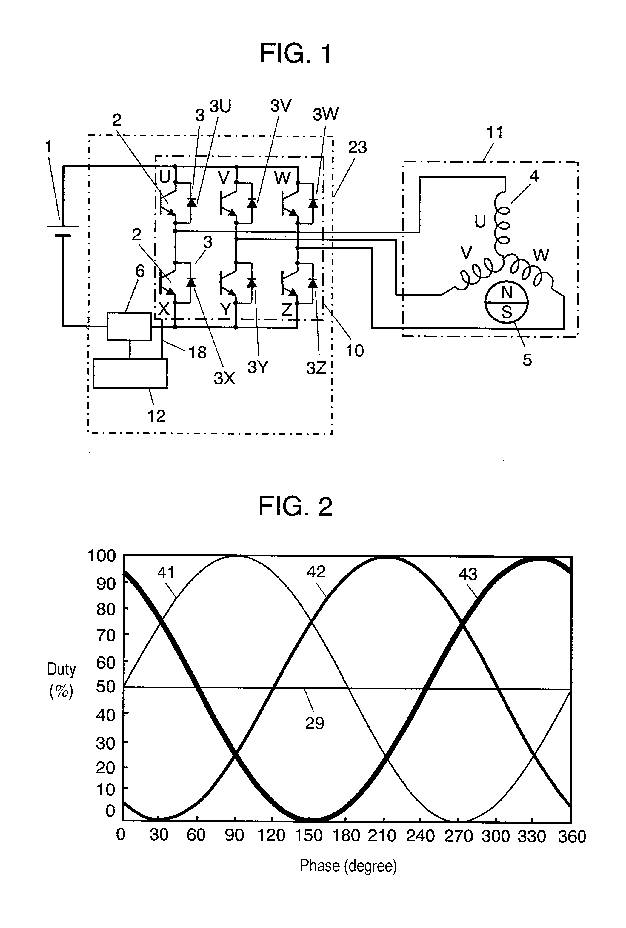
[0074]FIG. 1 is an electric circuit diagram showing an inverter device and the peripheral structure in accordance with the first exemplary embodiment of the present invention. Receiving voltage from current sensor 6 disposed on a power source line, control circuit 12 of inverter device 23 detects phase current. Control circuit 12 detects current in two phases and calculates the current value of the rest of the three phases from the detected two current values. In the calculation, Kirchhoff's law is applied to a neutral point of stator winding 4.

[0075]Using the three current values, control circuit 12 detects the position of magnet rotor 5 that constitutes sensorless DC brushless motor 11 (hereinafter, motor 11) by calculating induced voltage of stator winding 4. According to a revolution speed instruction signal (not shown) and the like, control circuit 12 controls switching elements 2 of inverter circuit 10 so that DC voltage from battery 1 is switched by PWM driving. Through the m...

second exemplary embodiment

[0103]The structure of the second exemplary embodiment will be described with reference to FIGS. 21 through 24. FIG. 21 shows behavior of each phase current in a case where a first correction is applied to the carrier cycle on the left and a second correction is applied to the carrier cycle on the right. The left-side carrier cycle is corrected in a manner that 2δ is added to the beginning of the ON period of the W-phase in FIG. 18 and 2δ is also added to the U-phase and the V-phase so as to be evenly shared between the beginning and the end of the ON period. The correction allows the current sensor to have time δ for detecting the W-phase current in the beginning and the end of the ON period, so that the W-phase current is detectable. In the left-side carrier cycle, a negative-going ripple appears in U-phase current iU and V-phase current iV, whereas a positive-going ripple appears in W-phase current iW.

[0104]On the other hand, the right-side carrier cycle is corrected in a manner ...

third exemplary embodiment

[0109]The structure of the third exemplary embodiment will be described with reference to FIGS. 25 through 29. According to the structure of the embodiment, current in two phases is detected on the four-carrier-cycle basis, i.e., one phase-current is detected on the two-carrier-cycle basis.

[0110]The left-side carrier cycle of FIG. 25 is so formed that time δ is added to the beginning of the ON period of the W-phase in FIG. 18. The U-phase and the V-phase have no addition. The correction above allows the current sensor to have time δ for detecting the W-phase current in the beginning of the ON period, that is, the W-phase current is detectable. U-phase current iU and V-phase current iV change in the negative direction, whereas W-phase current iW changes in the positive direction. On the other hand, the right-side carrier cycle of FIG. 25 is so formed that time δ is subtracted from the beginning of the ON period of the W-phase in FIG. 18. The subtraction cancels out the addition provi...


PUM


Abstract

The inverter device contains the following structure: an inverter circuit which has upper-arm switching elements that are connected on a positive side of a DC power source and lower-arm switching elements that are connected on a negative side of the DC power source; a current sensor that detects current flowing between the DC power source and the inverter circuit; and a control circuit that controls the inverter circuit by a PWM driving so that the inverter circuit outputs AC current to the motor. The control circuit provides a carrier cycle with a first correction and provides the successive cycle with a second correction, by which the current sensor can detect phase current of the motor. A ripple current caused by the first correction and a ripple current caused by the second correction are opposite in polarity.

Description

TECHNICAL FIELD[0001]The present invention relates to phase-current detection of an inverter device that operates on a pulse-width modulation (PWM) system.BACKGROUND ART[0002]For example, Japanese Patent Unexamined Publication No. 2004-282884 discloses a method of detecting phase current from a DC power line, which is a conventionally well-known method.[0003]The conventional structure will be described hereinafter with reference to a circuit diagram shown in FIG. 37. According to a revolution speed instruction signal (not shown) and the like, control circuit 107 of inverter device 120 controls switching elements 102 for converting DC current fed from battery 101 into AC current. The AC current is fed to stator winding 104 of a motor, by which magnet rotor 105 is driven. Diodes 103 form a circulating route of current flowing to stator winding 104. Current sensor 106 detects the current value and sends it to control circuit 107. Control circuit 107 uses the value for calculation of po...

Claims


Application Information

Patent Timeline
Patent Type & Authority Applications(United States)
IPC IPC(8): F04B35/04H02P27/08H02P1/04
CPCB60L1/003B60L2210/20H02M3/33576H02M2001/0009Y02T10/725H02M2001/0058H02M7/5395H02M3/3376H02M1/0009H02M1/0058Y02T10/72
Inventor GOTO, NAOMIKURAHASHI, YASUFUMI
Owner PANASONIC CORP
Why Eureka
Try Eureka