Multi-group transmission of a motor vehicle

a transmission and motor vehicle technology, applied in the direction of toothed gearings, gearing elements, gearings, etc., can solve the problems of slowed driving speed on an uphill incline, restrictions on driving performance, and interruption of traction, so as to achieve efficient and low-wear operation

Inactive Publication Date: 2009-10-22
ZF FRIEDRICHSHAFEN AG
View PDF7 Cites 27 Cited by
  • Summary
  • Abstract
  • Description
  • Claims
  • Application Information

AI Technical Summary

Benefits of technology

[0012]Against this background, the object of the invention is to disclose a multi-group transmission and a method for operating it which enables gear shifting

Problems solved by technology

Because of their type of construction, conventional multi-group transmissions, like all manual or automated transmissions that do not shift when under load, are subject to an interruption of traction during gear shifting, because the power flow from the drive motor is interrupted by disengaging a clutch to engage the gear without load, synchronizing the transmission and the drive motor at one coupling rotational speed in a neutral position, and engaging the target gear.
This imposes restrictions on driving performance, due to a loss of speed, and possibly greater fuel consumption.
Although in passenger cars, interruptions in traction are, as a rule, more likely to have only a bothersome effect on driving dynamics, for example with a sporty driving style, in the case of heavy c

Method used


Image

  • Multi-group transmission of a motor vehicle
  • Multi-group transmission of a motor vehicle
  • Multi-group transmission of a motor vehicle

Examples


Embodiment Construction

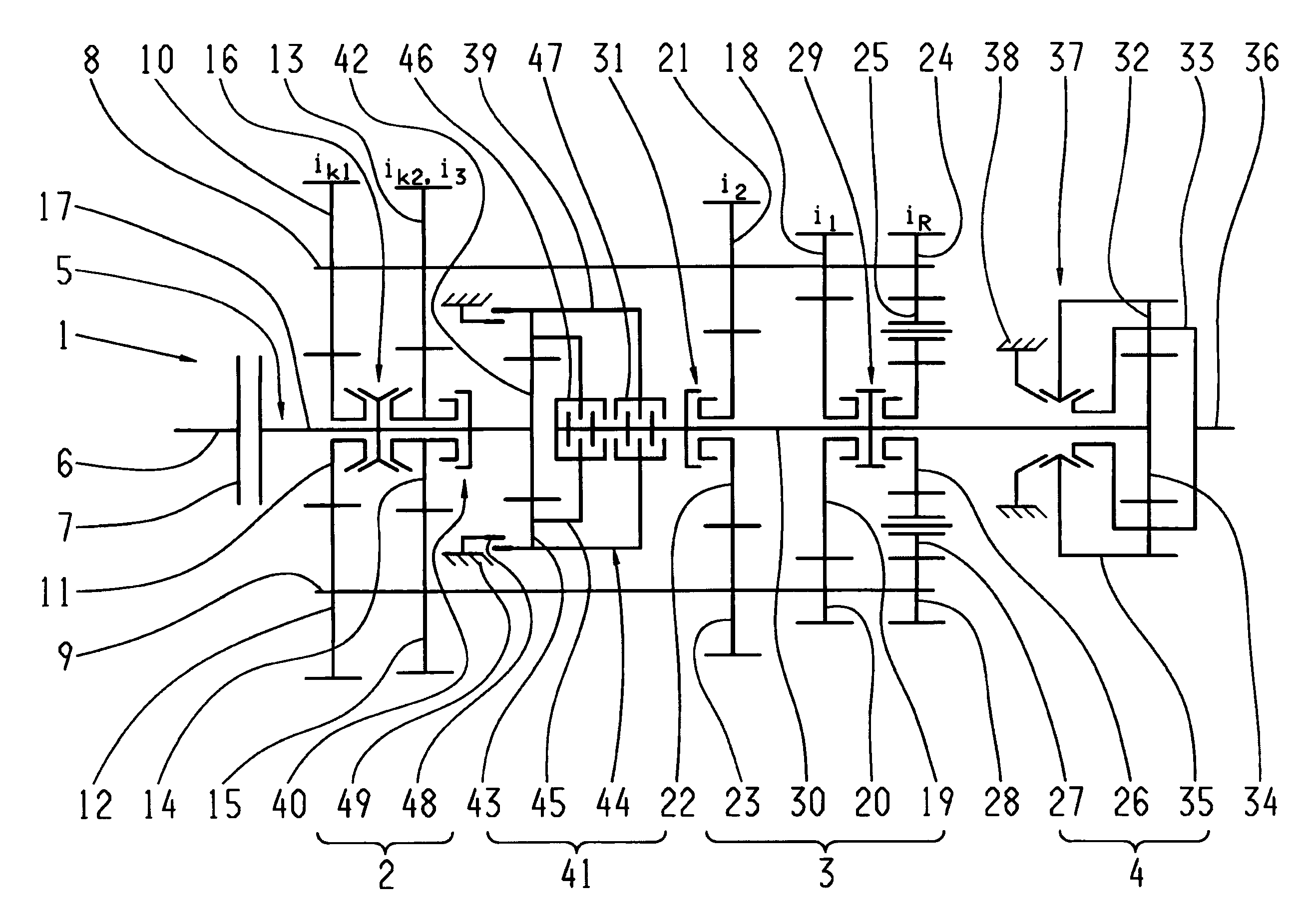
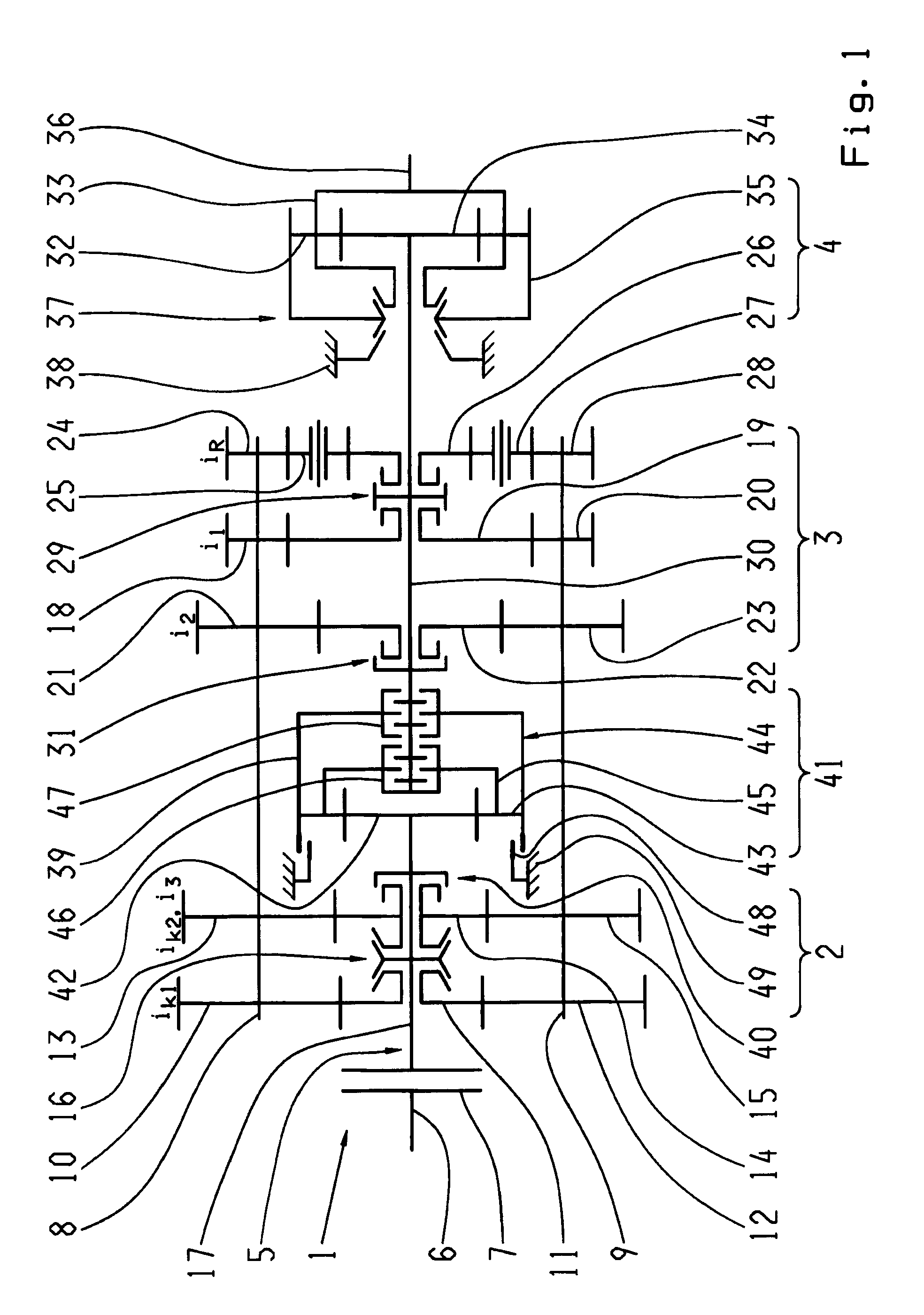
[0036]FIG. 1 accordingly shows an automated manual multi-group transmission configured as a dual-shaft transmission 1 with two parallel, rotatably mounted countershafts 8, 9 and three transmission groups 2, 3, 4, arranged one after the other, as could be provided, for example in the drive train of a truck. This kind of transmission as such, that is, without intermediate gear shifting, is known, for example, from the type series ZF-AS Tronic, and with intermediate gear coupling from DE 10 2006 024 370 A1 of the applicant, as cited at the beginning. A conventional starting element 7 in the form of a clutch is arranged between a drive shaft 6 of a drive motor that is not depicted in more detail and a transmission input 5. The transmission group 2, arranged at the transmission input 5, is designed as a dual-gear splitter transmission. The second transmission group 3 forms a three-gear main transmission. A dual-gear range change group is arranged downstream as a third transmission group ...


PUM


Abstract

The invention relates to a multi-group transmission of a motor vehicle with at least two transmission groups (2, 3) arranged in a drive train, in which the means for switching an intermediate gear are provided, in order to diminish or avoid interruptions in tractive force during gear changes. A planetary transmission (41) is arranged between a first transmission group (2) and a second transmission group (3), in order to enable gear changes without interruptions in tractive force with a variably selectable intermediate gear, as well as efficient operation that involves as little wear as possible, whereby a transmission input shaft (17) can be brought into a functional connection with a transmission main shaft (30) via the planetary transmission (41). According to a method of operating the multi-group transmission, a functional connection is established between a transmission input shaft (17) and a transmission main shaft (30), in order to switch an intermediate gear with the help of a planetary transmission (41) which can be engaged by means of the associated clutches (46, 47), so that at least one main group (3) is load-free, when a starting element (7) arranged between a drive motor and the transmission main shaft (17) is at least partially closed, an engaged initial gear is disengaged, the rotational speed of the drive motor in a slippage mode of at least one of the clutches (46, 47) of the planetary transmission (41) is synchronized with a connecting rotational speed of a target gear, and, when the connecting rotational speed is reached, a target gear is engaged, and the planetary transmission (41) is one again deactivated.

Description

[0001]This application claims priority from German patent application serial no. 10 2008 001 201.7 filed Apr. 16, 2008.FIELD OF THE INVENTION[0002]The invention relates to a multi-group transmission of a motor vehicle and a method of operating a multi-group transmission of a motor vehicle.BACKGROUND OF THE INVENTION[0003]Multi-group transmissions are comprised of one or more transmission groups that are usually serially arranged, by means of whose combination a large number of gears can be realized. They are increasingly conceived as automated manual transmissions, consisting, for example, of an input group, a main group, and a downstream group. Transmissions of this kind are used particularly in commercial vehicles, since they offer particularly fine gear shifting with 12 or 16 gears, for example, and feature a high degree of efficiency. With a smaller number of gears, configurations consisting only of a main group and an input group or a main group and a downstream group are also ...

Claims


Application Information

Patent Timeline
IPC IPC(8): F16H37/06
CPCF16H3/095F16H37/042F16H37/046F16H2061/0425F16H61/702F16H2003/0818F16H61/0403
Inventor DITTRICH, ALANHOFFMANN, RAYK
Owner ZF FRIEDRICHSHAFEN AG
Why Eureka
Try Eureka