
Surgical device and method

a surgical device and a technology of a surgical device, applied in the field of surgical devices and methods, can solve the problems of widening the bone socket aperture, abrading the tendon or other graft material, loosening, failure or degradation of the graft,

Inactive Publication Date: 2009-10-22
USHIBA JAMES
View PDF23 Cites 12 Cited by
  • Summary
  • Abstract
  • Description
  • Claims
  • Application Information

AI Technical Summary

Benefits of technology

[0020]Further alternatively or additionally, in certain other alternate preferred embodiments of the method of the present invention a tapered section may be disposed between the tip and the tail in order to reduce a possibility that the cannulated screw will be obstructed when being driven along the tail and onto the tip.
[0021]Even further alternatively or additionally, in certain other alternate preferred embodiments of the method of the present invention a the tip and the tail may present an equal or substantially equal radius in order to reduce a possibility that the cannulated screw will be obstructed when being driven along the tail and onto the tip.

Problems solved by technology

Furthermore, there is a well-described phenomenon (or “windshield wiper effect”) whereby a reconstructed ligament with a fixation point far from the joint, may move back and forth with joint activity, therefore widening the bone socket aperture, abrading the tendon or other graft material, and causing loosening, failure or degradation of the graft.
Although interference screw attachment generally is secure, it is sometimes neither possible nor desirable to provide such fixation, particularly in the femoral socket.
In revision situations, for example, where a previous reconstruction has been performed, placing a second femoral tunnel close to the previous socket may not be medically advisable.
The technique is disadvantageous, however, because the graft can become wrapped around the implant as it is rotated.
In addition, this technique requires a forked insertion tool to lift the tendon graft into the femoral socket, and large tibial and femoral tunnels are needed to accommodate the forked insertion tool.

Method used


Image

  • Surgical device and method
  • Surgical device and method
  • Surgical device and method

Examples


Embodiment Construction

[0047]In describing the preferred embodiments, certain terminology will be utilized for the sake of clarity. Such terminology is intended to encompass the recited embodiment, as well as all technical equivalents, which operate in a similar manner for a similar purpose to achieve a similar result.

[0048]It is understood that elements depicted in the drawings may be embodied in varying dimensions are that the drawings are therefore not presented in a particular scalar representation but as representative sizes.

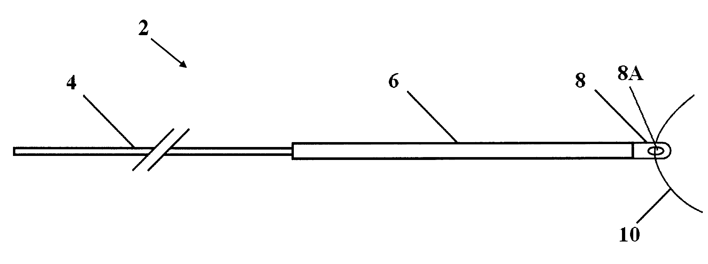
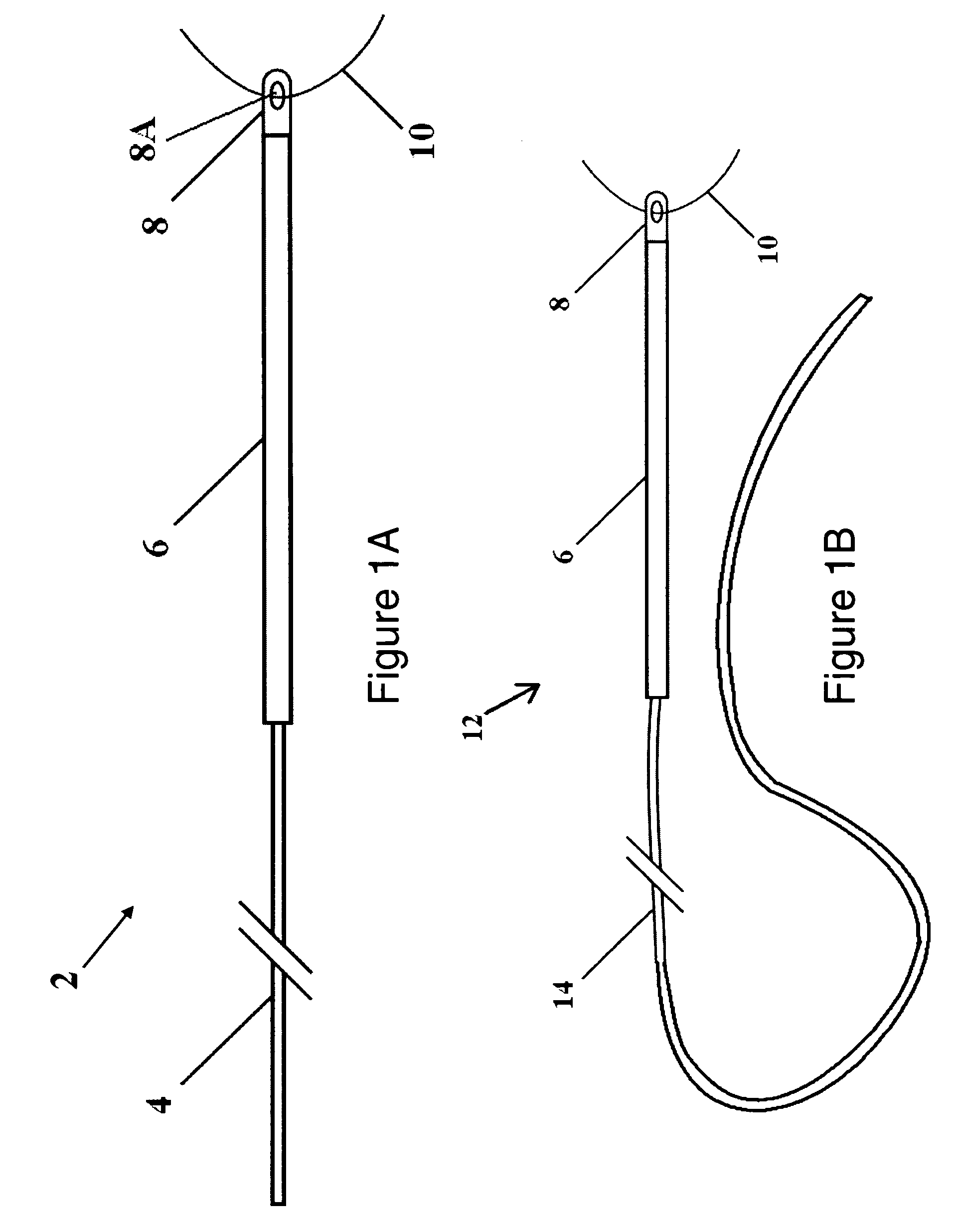
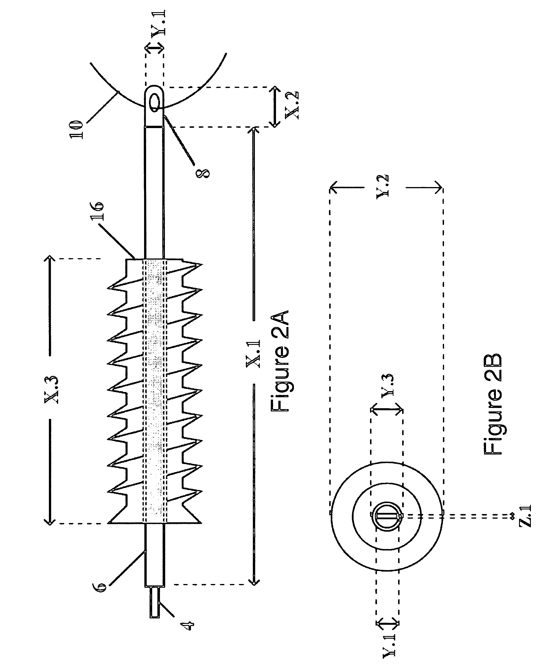
[0049]Referring now generally to the Figures and particularly to FIG. 1A, FIG. 1A is an illustration of a first version 2 of the present invention comprising a nitinol guide wire shaped into a tail 4, a tip 6, and a strand attachment feature 8. The strand attachment feature 8, or first attachment feature 8, is configured with an eye 8A that is sized and shaped to allow a surgical suture or wire 10 (hereafter “strand”10) to extend through the eye 8A. It is understood the strand 10...


PUM


Abstract

A surgical device and method for fixation of a tissue graft into a bone is disclosed. A strand is coupled with the tissue graft. A guide wire is coupled with the strand. The tissue graft is positioned within a socket of the bone and a cannulated screw is driven along the guide wire and into the bone socket to form an interference fixation of the tissue and the tissue graft. The strand attached to the tissue graft is retracted from the bone socket through a strand aperture of the socket. The guide wire is then removed from the bone socket. A loop may be transposed between, and coupling, the tissue graft and the strand. The guide wire may alternatively be coupled with the loop and / or the strand. The tissue graft may be a tendon tissue or a bone-tendon-bone graft.

Description

FIELD OF THE INVENTION[0001]The present invention relates to surgical devices and methods applied to position organic tissue into a bone structure. More particularly the present invention relates to the need to position a cannulated element in relation to a bone structure.BACKGROUND OF THE INVENTION[0002]The prior art provides guide wires that are used to position cannulated elements, e.g., screws, dilators, notchers and taps, for engagement with a human or other mammalian bone. In particular, guide wires are conventionally used to position cannulated screws for the purpose of forming a fixation of a tissue with a bone. The bone may be part of a joint structure, e.g., a human knee. Certain fixation types known in the art that employ interference screws to affix a bone block or a soft tissue graft to a bone include definitive fixation and adjuvant fixation. The prior art also provides for additional methods of fixation, such as endobutton techniques, trans-fixations, and rigid-fixati...

Claims


Application Information

Patent Timeline
Patent Type & Authority Applications(United States)
IPC IPC(8): A61B17/04A61B19/00
CPCA61B17/842A61B17/864A61B17/8645A61B17/8861A61B17/8872A61B17/8897A61F2002/0888A61F2/0805A61F2/0811A61F2002/0858A61F2002/087A61F2002/0882A61B2017/00867
Inventor USHIBA, JAMES
Owner USHIBA JAMES
Learn More