Optical Sighting System

a sighting system and optical technology, applied in the direction of mechanical control devices, instruments, process and machine control, etc., can solve the problems of difficult task, limited sighting system for civilian, law enforcement, military firearms used for adjusting the orientation of firearms, and difficulty in selecting a proper firing position

Active Publication Date: 2009-10-29
WINDAUER BERNARD T +1
View PDF36 Cites 62 Cited by
  • Summary
  • Abstract
  • Description
  • Claims
  • Application Information

AI Technical Summary

Benefits of technology

[0014]The present inventive concept automatically solves the equations of motion of a projectile from a muzzle to a target in near real time and, under all applicable conditions of firing, provides correct aiming adjustments to a sighting system based on the automatically solved equations in order to impact the target, all of which facilitate rapid aiming of the firearm under operational conditions in the field. The present inventive concept also provides a system that utilizes feedback information related to a state of at least one optical adjustment to either (1) enable the corresponding adjustor to accomplish a commanded adjustment quickly and accurately, or (2) confirm to the firearm operator that the commanded adjustment has been accomplished before firing the firearm.
[0018]The present inventive concept also provides a method for automatically determining optical adjustments to an optical sighting system having at least one optical adjustment in which a condition indication signal is generated that is based on a detected condition that affects the trajectory of a projectile between an origin and a selected target, a state indication signal is generated based on a state of an optical adjustment of the optical sighting system, and at least one adjustment for the adjustable optical system is determined based on at least one condition indication signal and one state indication signal so that the projectile will have a trajectory between the origin and the selected target that helps the projectile to hit the target.
[0019]Further, the present inventive concept provides a computer-readable storage medium containing a set of machine-executable instruction for performing a method for automatically determining optical adjustments to an optical sighting system having at least one optical adjustment, such that the method includes receiving a condition indication signal based on a detected condition that affects the trajectory of a projectile between an origin and a selected target, receiving a state indication signal based on a state of an optical adjustment of the optical sighting system, and determining at least one adjustment for the adjustable optical system based on at least one received condition indication and at least one received state indication signal so that the projectile will have a trajectory between the origin and the selected target that helps the projectile to hit the target.
[0021]The present inventive concept also provides a method of manufacturing an automatic optical sighting system that includes providing an adjustable optical system having at least one optical adjustment, providing at least one sensor such that each sensor detects a condition that affects a trajectory of a projectile between an origin and a selected target and generates an indication of the detected condition, and providing a processor receiving information related to each detected condition and information related to a state of at least one optical adjustment, the processor determining at least one adjustment for the adjustable optical system based on at least one detected condition and the state of the at least one optical adjustment so that the projectile will have a trajectory between the origin and the selected target that helps the projectile to hit the target.
[0022]Still further, the present inventive concept provides a method of manufacturing an automatic optical sighting system that includes providing an adjustable optical system having at least one optical adjustment, providing at least one sensor such that each sensor detecting a condition that affects a trajectory of a projectile between an origin and a selected target and generating an indication of the detected condition, providing a processor and providing a housing. The processor receives information related to each detected condition and determines at least one adjustment for the adjustable optical system based on at least one detected condition so that the projectile will have a trajectory between the origin and the selected target that helps the projectile to hit the target. The housing contains at least one actuator. The actuator corresponds to an optical adjustment of the optical system and is responsive to the determination of the processor by adjusting the optical adjustment based on the determination. The actuator is located internal to the housing.

Problems solved by technology

Existing sighting systems for civilian, law enforcement, and military firearms that are used for adjusting the orientation of a firearm are limited by the training of the marksman to judge ambient conditions at the location and time when a shot is taken.
Further, due to variable target distances, atmospheric conditions and geographic conditions at the time of firing, a marksman must consider many variables in combination to determine the optimal sighting-system settings for hitting an intended target, thus presenting a difficult task.
Further difficulties in selecting a proper firing position are caused by secondary effects, such as Coriolis acceleration and Yaw of Repose deflection.
Such secondary effects may have inconsequential effects on firing accuracy at shorter ranges, but can cause impact misses at long ranges.
Additionally, in some military and law enforcement scenarios, range distances are shorter than 1000 meters, but targets appear very small, requiring secondary effects to be considered.
A significant drawback, however, is that in-field use, a problem of stepper motor failure caused by dirt and moisture or mud build-up between the body of the scope and the body of the firearm can prevent a stepper motor from producing a desired adjustment.
Other drawbacks that are associated with the Kaladgew system include that Kaladgew does not disclose how windage adjustments are made, i.e., how the data is collected and processed, and how commands to a windage stepper motor are generated.
Kaladgew also does not address incorporation of secondary factors when calculating telescopic sight adjustments, which, as discussed above, can play a significant role in long-distance target shooting, or in situations in which extreme precision is required.
Additionally, Edwards provides no manual override for adjusting a telescopic sight in the event of electrical failure.
Further, Edwards does not calculate or implement corrections for secondary effects (e.g., Coriolis Effect, gyroscopic effects) that may have significant impact on accuracy in long-range target situations.
Thus, a major drawback of both Kaladgew and Edwards is that neither automatically solves the equations of motion of a projectile from a muzzle to a target in near real time and, under all applicable conditions of firing, provides correct aiming adjustments to a sighting system based on the automatically solved equations to impact the target.
Another serious drawback of both Kaladgew and Edwards is that neither patent makes use of feedback information related to a state of at least one optical adjustment to either (1) enable the corresponding adjustor to accomplish a commanded adjustment quickly and accurately, or (2) confirm to the firearm operator that the commanded adjustment has been accomplished before firing the firearm.

Method used


Image

  • Optical Sighting System
  • Optical Sighting System
  • Optical Sighting System

Examples


Embodiment Construction

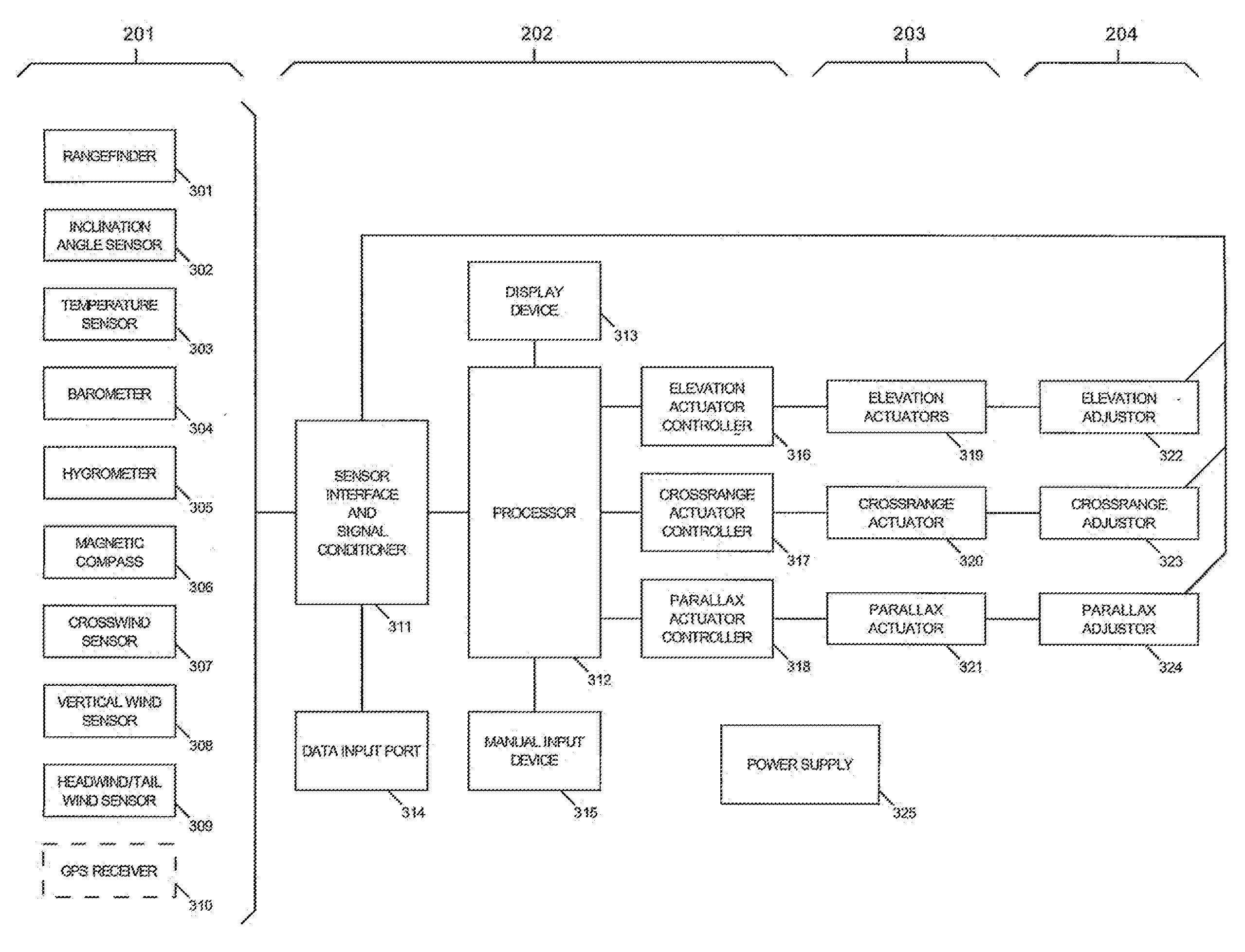
[0044]The present inventive concept provides an automatic optical sighting system (AOSS). When used with a firearm, the AOSS of the present inventive concept automatically performs one or more aiming adjustments, thereby eliminating the need for a marksman to estimate the effects of, for example, range to the target, ambient weather conditions, direction of the target from the firearm, inclination angle of fire, and projectile characteristics. Additionally, exemplary embodiments of the present inventive concept provide automatic aiming adjustments that are necessary for compensating for one or more secondary effects that may affect accuracy of projectile impact at range distances in excess of about 800 meters, as well as accuracy of projectile impact for smaller targets at closer range distances. The exemplary embodiments of the present inventive concept also allow a manual override of one or more adjusters that adjust, for example, elevation, windage, or parallax, in the event of a...


PUM

PropertyMeasurementUnit
range distancesaaaaaaaaaa
distancesaaaaaaaaaa
trajectoryaaaaaaaaaa

Abstract

An automatic optical sighting system generates at least one adjustment for an adjustable optical system based on at least one detected condition, an appropriate dynamic model of a projectile in flight, and a solution of the equations of motion in flight, so that the projectile will have a trajectory between an origin and a selected target that helps the projectile to hit the target.

Description

CROSS-REFERENCE TO RELATED PATENT APPLICATIONS[0001]The present patent application claims priority from U.S. Provisional Application Ser. No. 60 / 632,331, filed Nov. 30, 2004, U.S. Provisional Application Ser. No. 60 / 638,561, filed Dec. 22, 2004, and PCT Patent Application No. PCT / US05 / 43335, filed Nov. 30, 2005, the contents of each are hereby incorporated by reference herein.BACKGROUND OF THE INVENTION[0002]The present inventive concept relates to an automatic optical sighting system (AOSS) that may be used with an optical enhancement device, such as a telescopic sight for use with a civilian or military individual shoulder- or hand-fired firearm, or in any firearm classified as a line-of-sight or a “small arm” firearm that is on a mechanical mount for stability or portability.[0003]FIG. 1 depicts a basic problem associated with aiming a firearm. Line of sight 110 of a shooter (also referred to herein as “marksman,”“operator,” or “user”) from a firearm 111 to a target 112 essential...

Claims


Application Information

Patent Timeline
Patent Type & Authority Applications(United States)
IPC IPC(8): F41G3/08
CPCF41G1/38F41G1/40F41G3/06F41G3/08Y10T74/2084G05G1/10G05G5/12Y10T74/1494Y10T29/49826G02B23/14
Inventor WINDAUER, BERNARD T.MCDONALDALMGREN, TED C.
Owner WINDAUER BERNARD T
Why Eureka
Try Eureka