
Spare tire assembly

a technology of spare tires and wheel wells, which is applied in the direction of wheel assembly, multiple wheel assembly, vehicle components, etc., can solve the problems of requiring a hazardous step of jacking up the vehicle, and the wheel wells may not be deep enough to allow for such excess tire width, so as to facilitate the installation of spare tires and facilitate rapid installation of spare tires

Inactive Publication Date: 2009-10-29
THOMPKINS TOREK
View PDF47 Cites 22 Cited by
  • Summary
  • Abstract
  • Description
  • Claims
  • Application Information

AI Technical Summary

Benefits of technology

[0007]Various embodiments of the current invention offer a method of installing a spare tire without requiring complicated tools or jacks. Various exemplary embodiments of the invention offer tools which may be used in place of standard lug nuts or lug bolts to facilitate installation of a spare tire without requiring tire replacement. In various exemplary embodiments, a system or kit for facilitating rapid installation of a spare tire is provided.
[0013]The spare tire assembly as described herein protects a wheel of a vehicle from damage from friction arising from direct contact between the rim of the wheel and an interior surface of a flat tire. Also, if the contact between the wheel and the interior surface of a flat tire causes the tire to split or rupture, the wheel is subject to damage from direct contact between the rim of the wheel and a road surface. The spare tire assembly as described herein prevents such contact, thereby protecting the wheel.

Problems solved by technology

In most cases, however, the original flat tire must still be removed from the vehicle, requiring a hazardous step of jacking up the vehicle.
Additionally, some cars have wheel wells which may not be deep enough to allow for such excess tire width.

Method used


Image

  • Spare tire assembly
  • Spare tire assembly
  • Spare tire assembly

Examples


Embodiment Construction

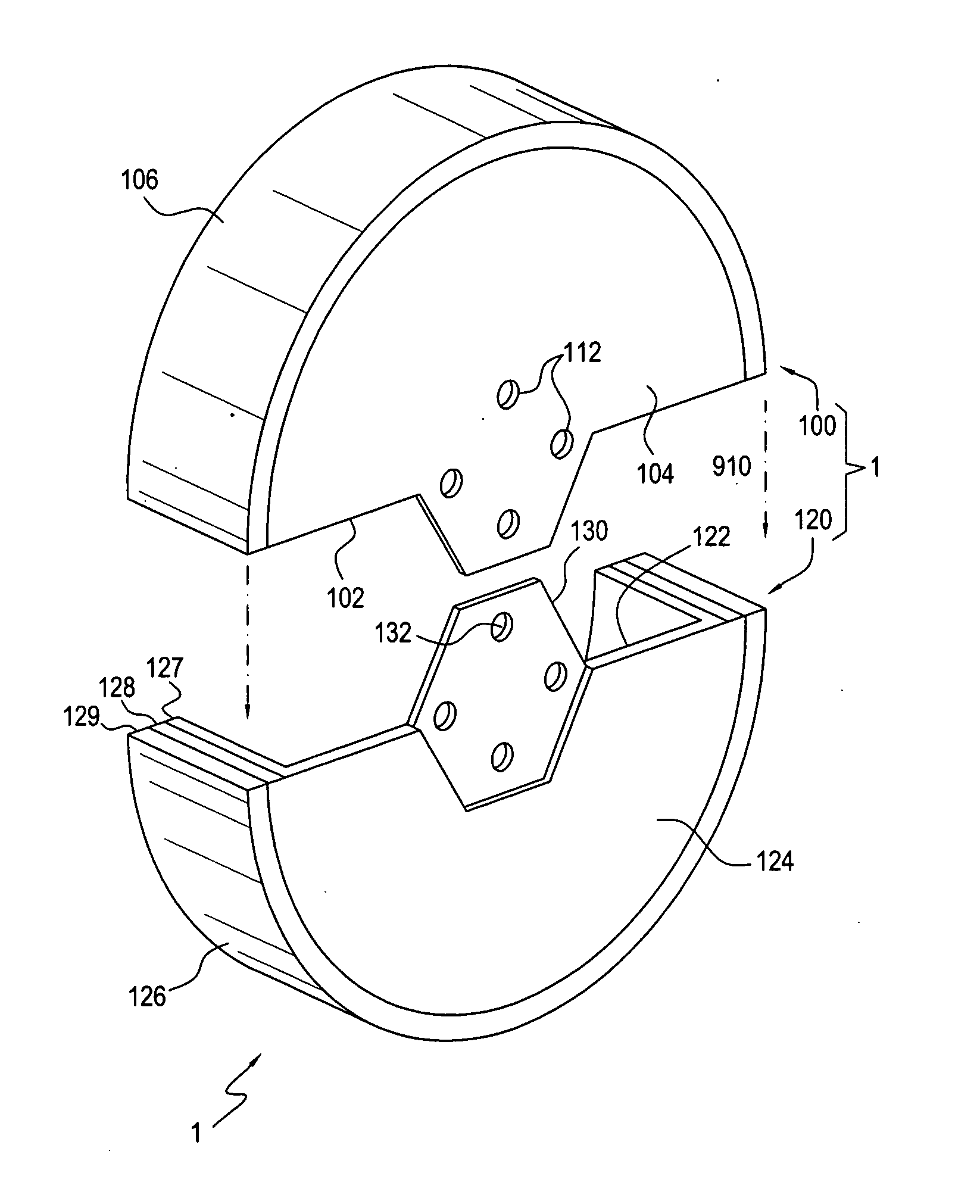
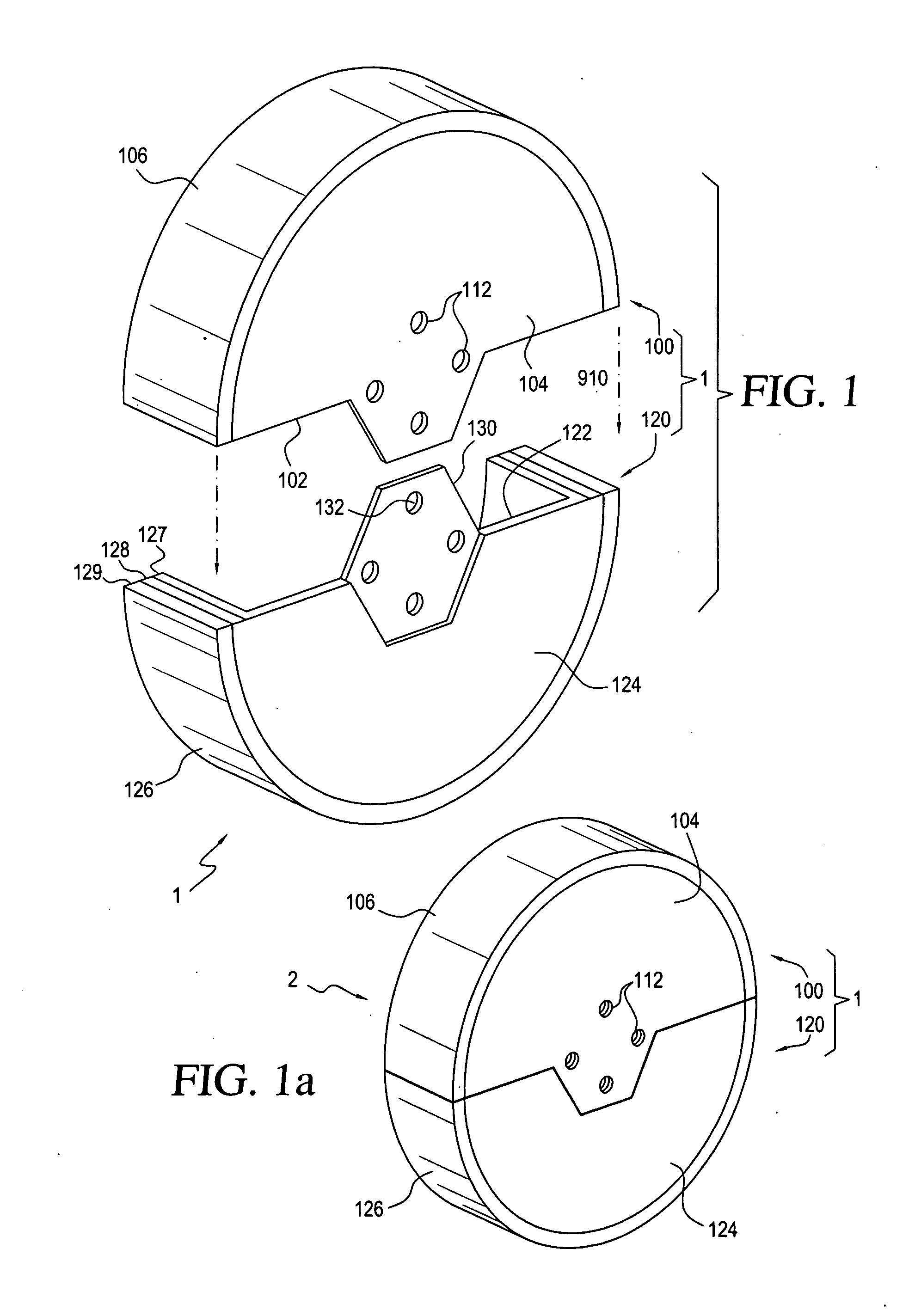
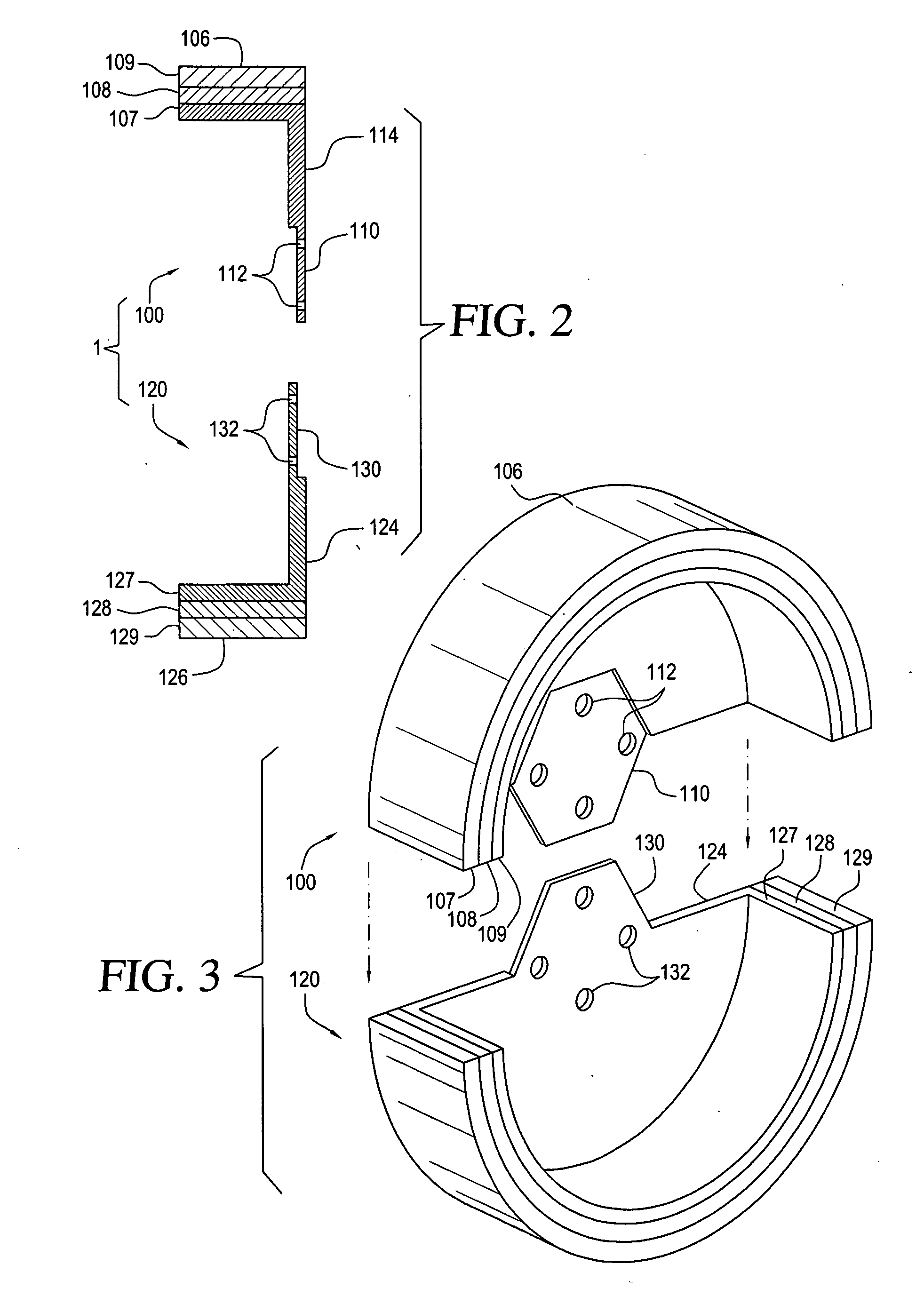
[0028]Referring now to the drawings, in which like numerals refer to like components or steps, there are disclosed broad aspects of various exemplary embodiments. FIG. 1 is a perspective view showing two halves, 100 and 120, of an exemplary embodiment of a spare tire assembly 1 according to the present disclosure. Referring first to tire half 120, tire half 120 includes a semi-cylindrical shell 122 having a first planar end surface 124 and a curved outer wall 126. Outer wall 126 is made of a laminated material having a rigid inner shell 127, an outer tread layer 129, and an optional intermediate cushioning layer 128. End surface 124 is secured to inner shell 127. End surface 124 and inner shell 127 may be integrally formed by molding them as a single unit, thermoforming them from sheet material, or stamping them from sheet metal. They are preferably formed from a metal such as steel, aluminum, titanium or alloys thereof, or from a thermoplastic or thermosetting polymer material. The...


PUM


Abstract

A wheel on a vehicle having a flat tire may be protected by attaching a first semi-cylindrical shell having a first planar end to the wheel, and attaching a second semi-cylindrical shell to the first semi-cylindrical shell. The first semi-cylindrical shell and the second semi-cylindrical shell are secured together so as to form a cylindrical shell of diameter having a cylindrical wall which covers a tread surface of the flat tire. The first semi-cylindrical shell is attached to the wheel to cover a first portion of a tread surface of the flat tire; and, after attaching the first semi-cylindrical shell, the wheel is rotated. The first portion of the tread surface does not contact a ground surface prior to the rotation step, but does contact a ground surface through the first semi-cylindrical shell after the rotation step. A connector for connecting the semi-cylindrical shells to the wheel is also disclosed.

Description

BACKGROUND OF THE INVENTION[0001]1. Field of the Invention[0002]The invention relates generally to the field of spare tires, and more particularly to spare tires that can be used to protect the wheel or wheel rim of a vehicle without requiring removal of the flat tire from the vehicle.[0003]2. Description of Related Art[0004]One of the most common maintenance procedures that a driver must perform is changing a flat tire. To change a flat, a driver must typically execute the following steps remove the lug nuts securing the wheel carrying the flat tire to the vehicle; remove the wheel from the vehicle; position a spare wheel bearing a flat tire on the vehicle; and secure the spare wheel to the vehicle by replacing the lug nuts.[0005]Various attempts have been made to provide a substitute for the traditional spare tire. A wide variety of modular spare tires comprised of a plurality of connecting segments have been proposed. In most cases, however, the original flat tire must still be r...

Claims


Application Information

Patent Timeline
Patent Type & Authority Applications(United States)
IPC IPC(8): B60B11/10
CPCB60C17/04B60B11/10
Inventor THOMPKINS, TOREK
Owner THOMPKINS TOREK
Learn More