
Structure for mounting vehicle driving apparatus

a technology for mounting structures and driving apparatuses, applied in the direction of structural associations, dynamo-electric machines, supports/encloses/casings, etc., can solve the problems of increasing costs and -described problems

Inactive Publication Date: 2009-10-29
TOYOTA JIDOSHA KK +1
View PDF14 Cites 10 Cited by
  • Summary
  • Abstract
  • Description
  • Claims
  • Application Information

AI Technical Summary

Benefits of technology

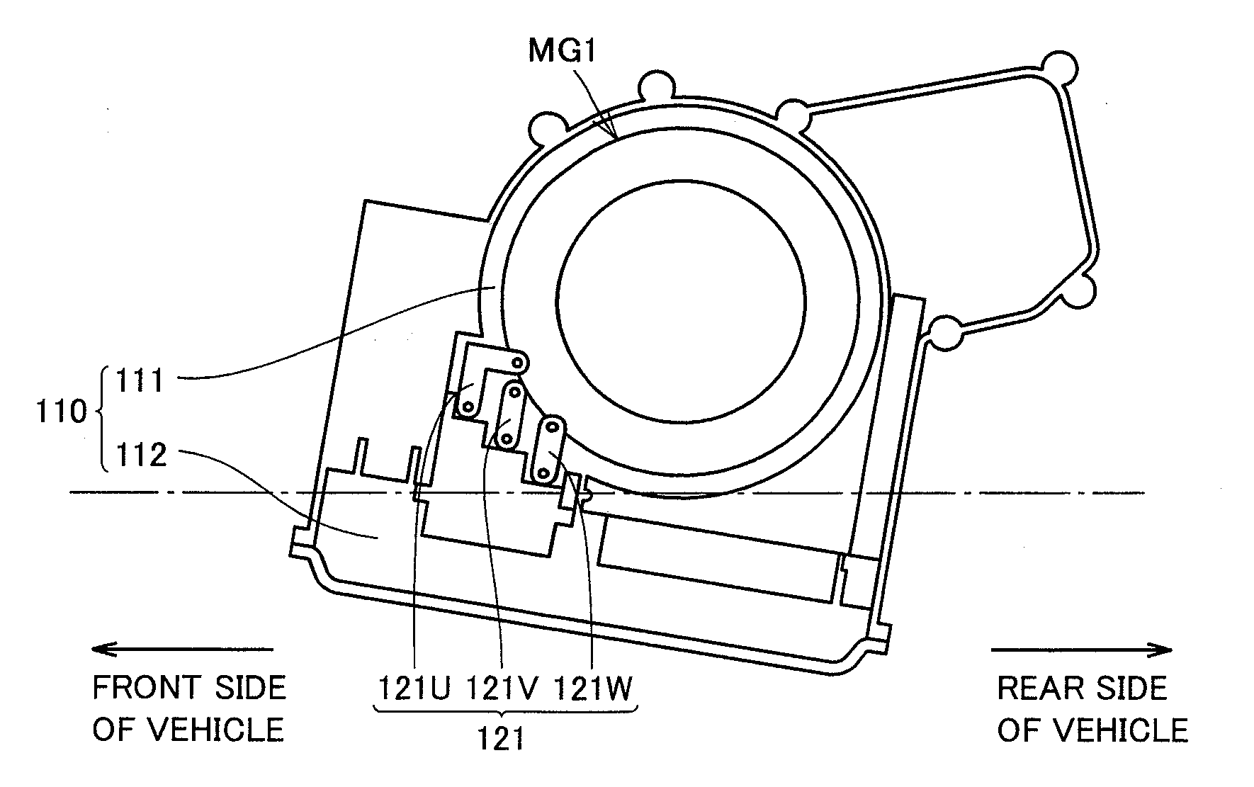
[0008]An object of the present invention is to provide a mounting structure for a vehicle driving apparatus in which a connecting terminal portion between a rotating electric machine and an electric unit is restrained from being immersed in the cooling medium for cooling the rotating electric machine.
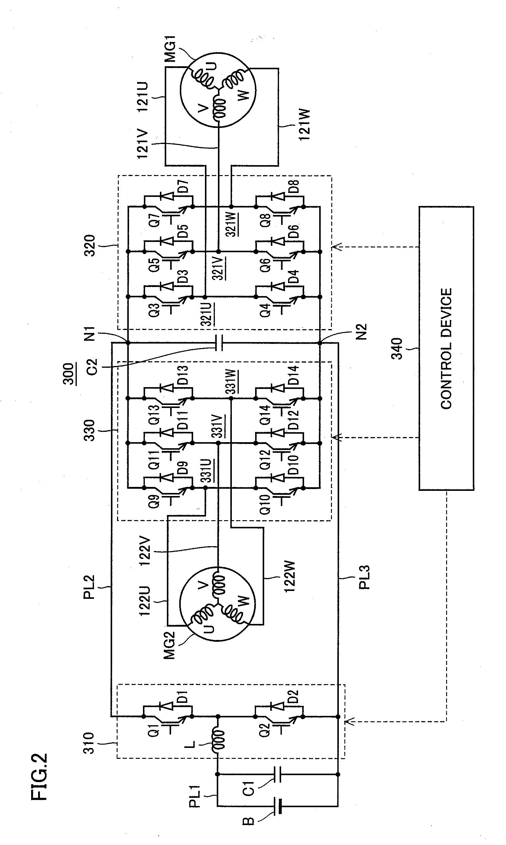
[0014]According to the above-described configuration, an electrical short circuit can be restrained from occurring between each of phase terminals connected to their respective phase coils.
[0016]According to the above-described configuration, the relative liquid level of the cooling medium with respect to the differential gear can be raised and the relative liquid level of the cooling medium with respect to the connecting portion can be lowered. Accordingly, the connecting portion can be restrained from being immersed in the cooling medium while preventing insufficient stirring up of the cooling medium by the differential gear.
[0017]According to the present invention, in the vehicle driving apparatus in which the rotating electric machine and the electric unit connected to the rotating electric machine are integrated with each other, it is possible to restrain the connecting terminal portion between the rotating electric machine and the electric unit from being immersed in the cooling medium for cooling the rotating electric machine.

Problems solved by technology

The immersion of the connecting terminal in the cooling medium requires particular measures to be taken in order to ensure the insulation performance in the connecting terminal, which results in an increase in cost.
Patent Documents 1-4 do not disclose the details of the structure of the connecting terminal, and thus, the above-described problems may arise.

Method used


Image

  • Structure for mounting vehicle driving apparatus
  • Structure for mounting vehicle driving apparatus
  • Structure for mounting vehicle driving apparatus

Examples


Embodiment Construction

[0024]The embodiments of the present invention will be hereinafter described. The same or corresponding components are designated by the same reference characters, and description thereof may not be repeated.

[0025]In the embodiments described below, when the number, the quantity and the like are mentioned, the scope of the present invention is not necessarily limited thereto unless otherwise specified. Also in the embodiments described below, each component is not necessarily essential to the present invention unless otherwise specified. Furthermore, in the case where there are a plurality of embodiments in the following description, it is originally designed to combine the characteristic portions of each embodiment as appropriate unless otherwise specified.

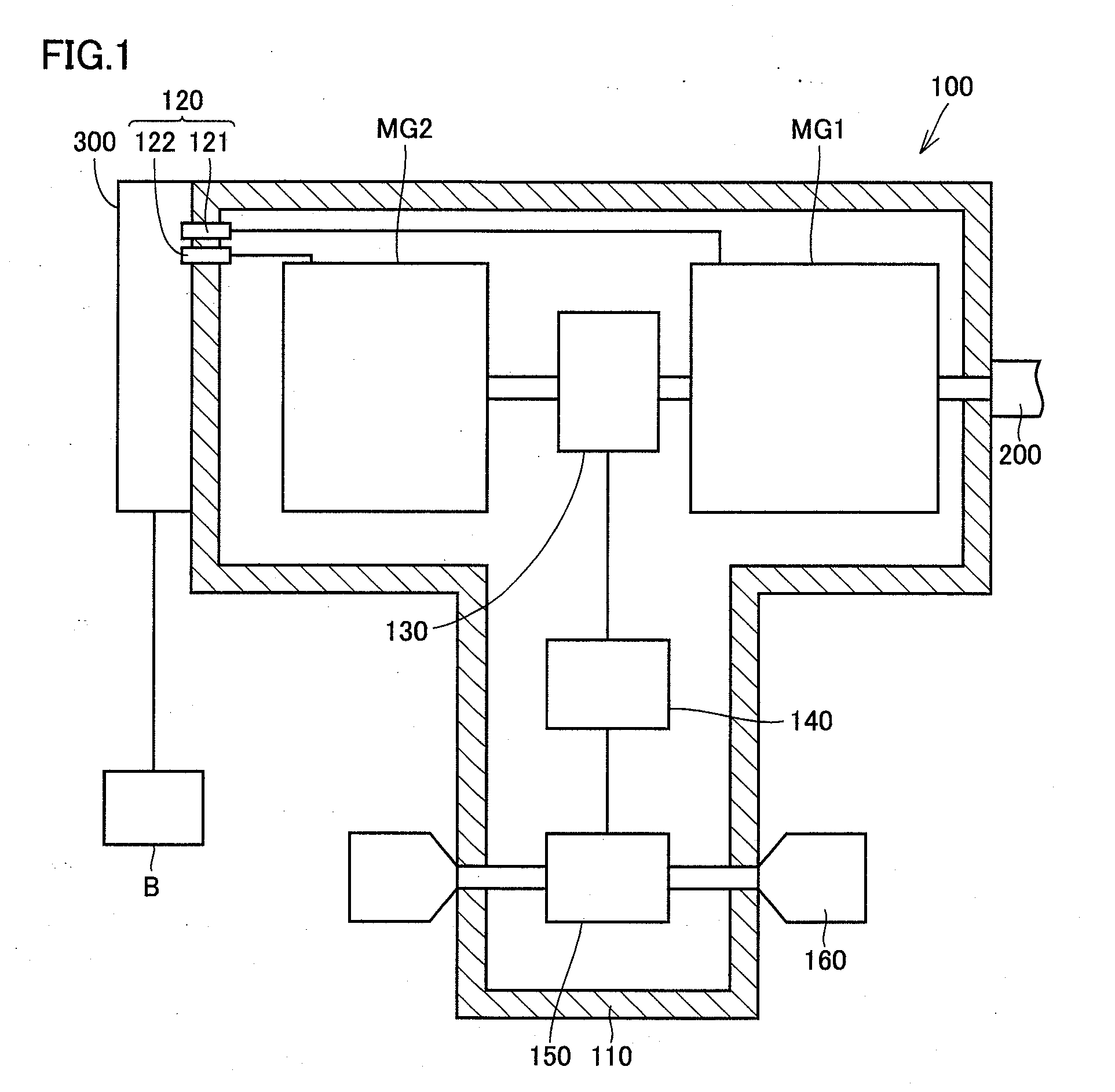
[0026]FIG. 1 shows a configuration of a vehicle driving apparatus to which a mounting structure according to one embodiment of the present invention is applied. Referring to FIG. 1, a driving apparatus 100 serves to drive a hybri...


PUM


Abstract

A mounting structure for a vehicle driving apparatus includes a housing fixed to a vehicle body and including a first internal space and a second internal space formed below the first internal space in the state of being separated from the first internal space; a motor generator provided in the first internal space of the housing; an inverter provided in the second internal space of the housing; and a terminal electrically connecting the motor generator and the inverter. Oil used for cooling the motor generator is stored in the bottom of the first internal space. The portion in the terminal located in the first internal space is located above the highest liquid level of the oil stored in the first internal space.

Description

TECHNICAL FIELD[0001]The present invention relates to a mounting structure for a vehicle driving apparatus, and particularly to a mounting structure for a vehicle driving apparatus in which a rotating electric machine and an electric unit connected to the rotating electric machine are integrated with each other.BACKGROUND ART[0002]The vehicle driving apparatus has been conventionally known which is structured such that a rotating electric machine and an electric unit electrically connected to the rotating electric machine are integrated with each other.[0003]For example, Japanese Patent Laying-Open No. 10-248198 (Patent Document 1) discloses an inverter-integrated motor in which a motor body is placed on the upper surface of a motor mount and an inverter device is housed within the motor mount.[0004]Similarly, Japanese Patent Laying-Open Nos. 2004-343845 (Patent Document 2), 2004-215355 (Patent Document 3), 2001-238405 (Patent Document 4), and the like disclose a vehicle driving app...

Claims


Application Information

Patent Timeline
Patent Type & Authority Applications(United States)
IPC IPC(8): H02K9/19H02K11/00
CPCH02K5/225H02K11/048H02K9/19H02K9/02H02K11/05
Inventor YOSHIDA, TADAFUMIYOSHINO, MASAKIHOTTA, YUTAKA
Owner TOYOTA JIDOSHA KK
Learn More