Image display device having memory property, driving control device and driving method to be used for same

a technology of image display device and memory property, which is applied in the direction of electric digital data processing, instruments, computing, etc., can solve the problems of affecting the display performance, affecting the response speed of the electrophoretic element, and the inability to change the image, etc., so as to achieve the adjustment of the lut required for obtaining an appropriate image, the effect of simple and easy adjustment of the lu

Active Publication Date: 2009-10-29
NEC LCD TECH CORP
View PDF18 Cites 41 Cited by
  • Summary
  • Abstract
  • Description
  • Claims
  • Application Information

AI Technical Summary

Benefits of technology

[0024]Moreover, by dividing a renewing period corresponding to the plurality of frames, during the first displaying period, gray level display of the renewed screen is performed by using only a high-order bit of gray level of the renewed screen and, during the second displaying period, gray level display is per

Problems solved by technology

On the other hand, the response speed of the electrophoretic element is slower than that of the liquid crystal display device and image switching cannot be made unless a voltage continues to be applied for a plurality of frame periods and, therefore, in the electrophoretic display device, a PWM (Pulse Width Modulation) driving method is used in which a constant voltage continues to be applied for a plurality of frame periods.
In the reset driving method, due to necessity of display of a redundant reset screen, there is a fear of degrading the display performance.
There is, however, another problem in that, as the gray level becomes multiple from 16→32→64 gray levels, the configuration of the LUT becomes the more complicated, which causes a difficulty in adjustment for obtaining an excellent image.
To satisfy this, a process of determining huge pieces of matrix data is required, thus causing the LUT adjustment required for obtaini

Method used


Image

  • Image display device having memory property, driving control device and driving method to be used for same
  • Image display device having memory property, driving control device and driving method to be used for same
  • Image display device having memory property, driving control device and driving method to be used for same

Examples


first exemplary embodiment

[0053]Hereinafter, exemplary embodiments of the present invention are described by referring to drawings.

Driving Method

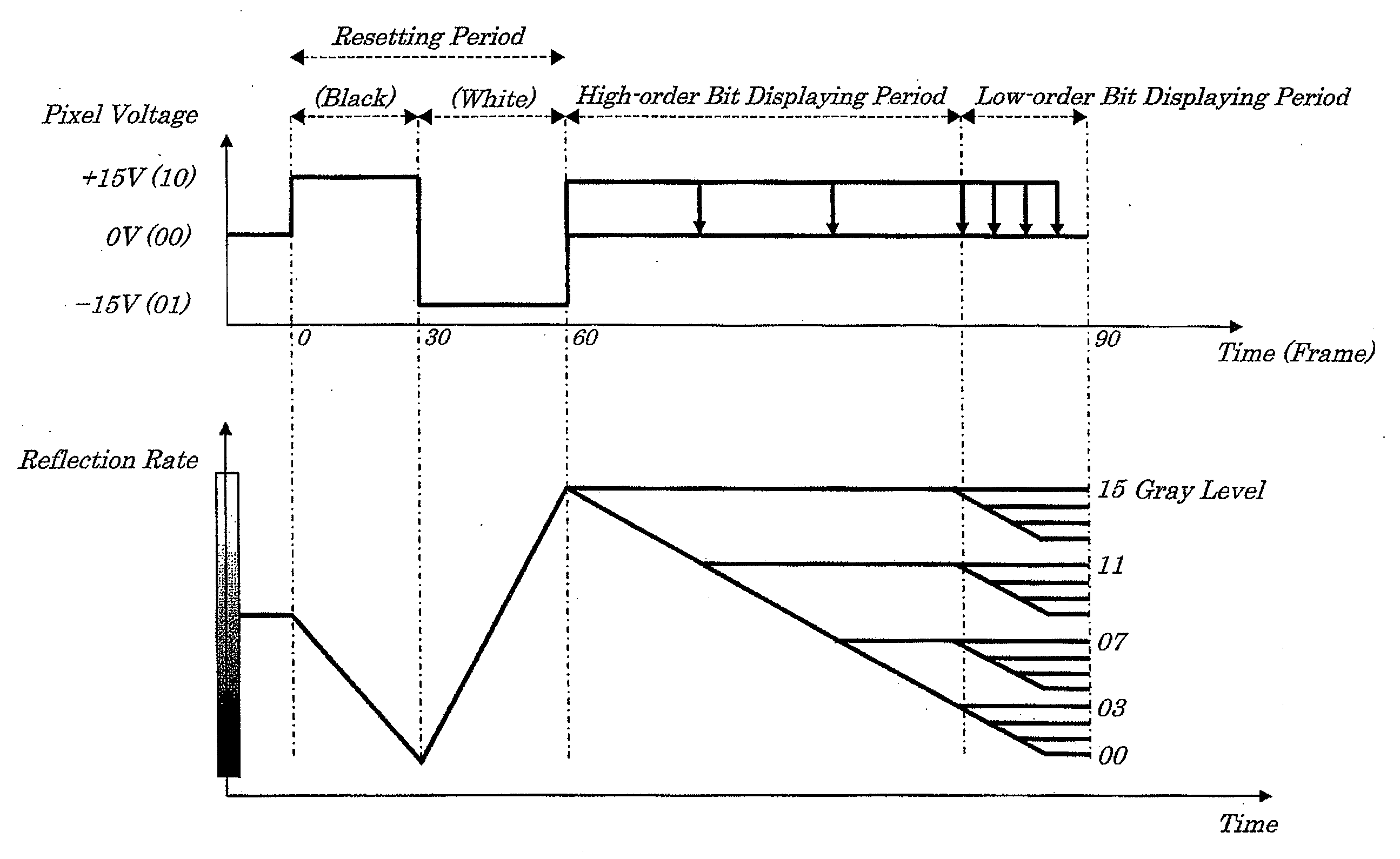
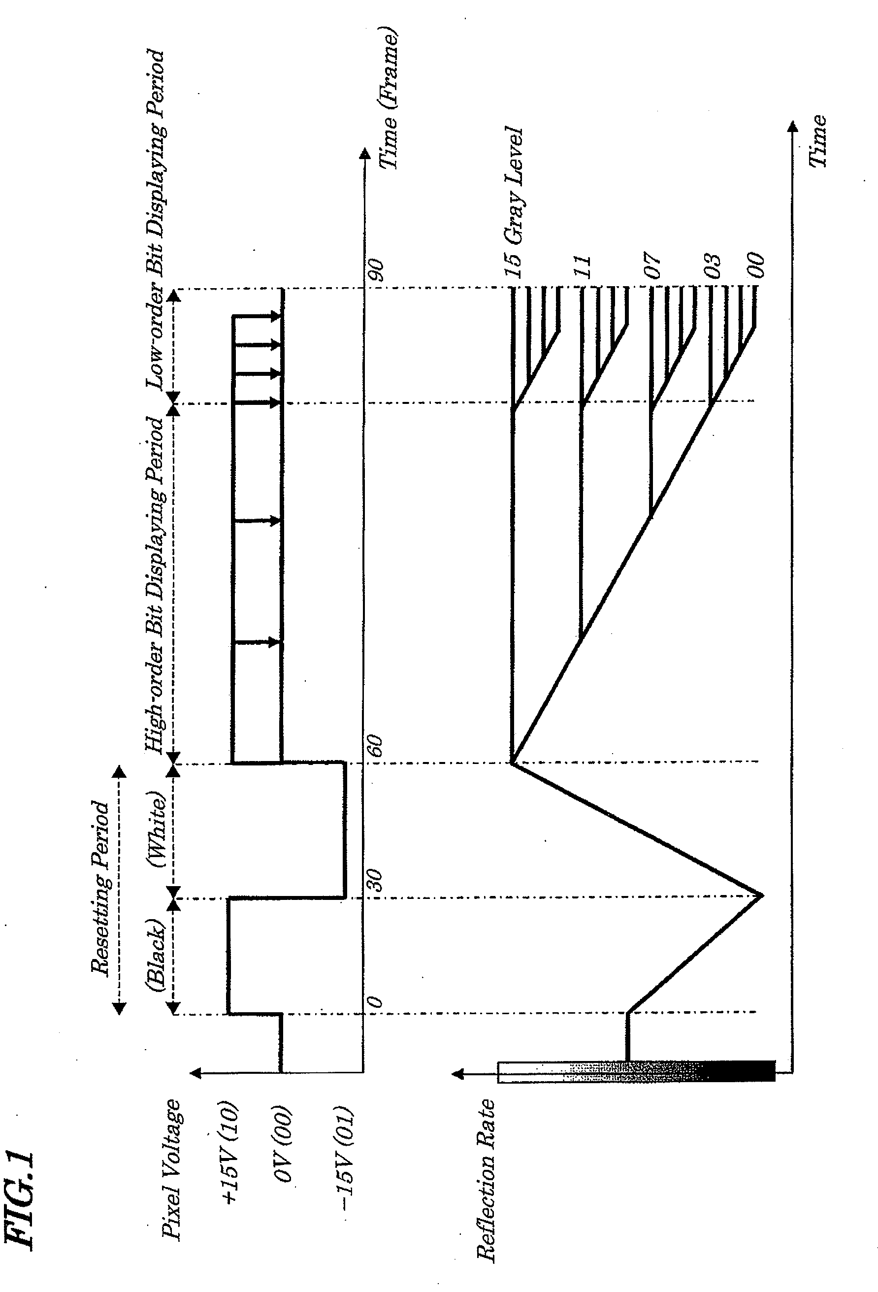
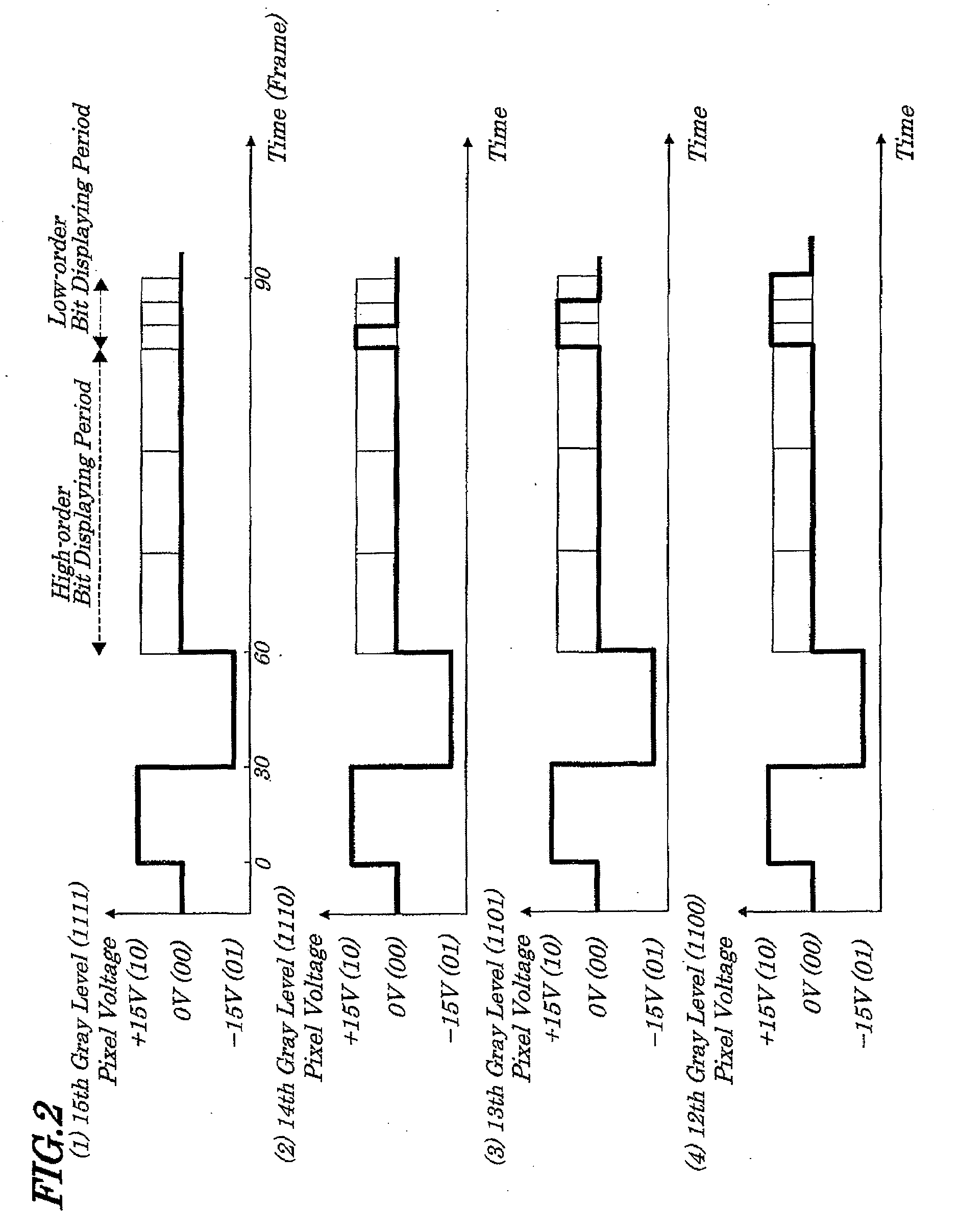
[0054]FIG. 1 is a diagram schematically showing a driving method for an electronic paper display device of the first exemplary embodiment of the present invention. FIGS. 2 to 5 are diagrams used to explain the driving method of the above electronic paper display device and are waveform diagrams showing driving voltage waveforms to be applied to pixel electrodes for every gray level in input gray level data.

[0055]The electronic paper display device of the present invention is an electrophoretic type display device made up of an electrophoretic display element having a memory property to be driven by an active matrix method and suitably used for electronic books and / or electronic newspapers.

[0056]First, a driving method to be employed in the electronic paper display device for display with multiple gray levels is described by referring to FIG. 1.

[0057]The driving meth...

second exemplary embodiment

[0133]Next, an electronic paper display device and a method of driving the same according to the second exemplary embodiment of the present invention are described.

[0134]FIG. 14 is a block diagram for showing electrical configurations of an electronic paper controller making up the electronic paper display device of the second exemplary embodiment.

[0135]The electronic paper controller 19A includes, as shown in FIG. 14, a data writing circuit 25, a display power circuit 26, an electronic paper control circuit 27A, a data reading circuit 28, an LUT converting circuit 29, and a clock generating circuit 34.

[0136]The configurations of the display device of the second exemplary embodiment differ greatly from those of the first exemplary embodiment only in that the clock generating circuit 34 is mounted which changes a frame frequency in the high-order bit displaying period and a frame frequency in the low-order bit displaying period. In FIG. 14, the same reference numbers are assigned to ...

third embodiment

[0138]Next, an electronic paper display device and its driving method according to the third exemplary embodiment of the present invention are described.

Driving Method

[0139]FIGS. 15(1) to 18(16) are diagrams provided to explain the driving method of the electronic paper display device of the third exemplary embodiment showing the driving voltage waveform to be applied to pixel electrodes for every gray level.

[0140]The driving method of the third exemplary embodiment is common to the driving method of the first exemplary embodiment (FIG. 1) in that a method of renewing a specified image by driving the device for a period of time corresponding to a plurality of frames. Multiple gray level display is realized by dividing a renewing period into a high-order bit displaying period and a low-order bit displaying period and by sequential driving the device for renewal of a screen.

[0141]However, the electronic paper display device and driving method of the third exemplary embodiment differ g...


PUM


Abstract

There is provided an image display device capable of obtaining a renewed screen giving normal feelings by simple LUT (Look Up Table) adjustment even at a time of displaying with multiple gray levels. A screen of the electronic paper section making up the display device is renewed by driving for a period of time corresponding to a plurality of frames according to input gray level data of a renewed screen. The renewed screen is displayed with a coarse gray level during a first displaying period in a renewing period corresponding to a plurality of frames at an output voltage specified by a high-order bit of its gray level data and, thereafter, is displayed with a fine gray level during a second displaying period in the renewing period at an output voltage specified by a low-order bit of its gray level data.

Description

INCORPORATION BY REFERENCE[0001]This application is based upon and claims the benefit of priorities from Japanese Patent Application No. 2008-107353, filed on Apr. 16, 2008 and Japanese Patent Application No. 2009-100415, filed on Apr. 16, 2009, the disclosures of which are incorporated herein in its entirely by reference.BACKGROUND OF THE INVENTION[0002]1. Field of the Invention[0003]The present invention relates to an image display device having a memory property, a driving control device and driving method to be used for the same; and more particularly to the image display device having a memory property being suitably used in an electronic paper display device such as an electronic book and electronic newspaper and to the driving control device and driving method to be used for the image display device.[0004]2. Description of the Related Art[0005]As a display device enabling an act of “reading” without the reader feeling stress, an electronic paper display device called an elect...

Claims


Application Information

Patent Timeline
IPC IPC(8): G09G5/10
CPCG09G3/2081G09G2300/08G09G3/344G09G2320/0252
Inventor SAKAMOTO, MICHIAKI
Owner NEC LCD TECH CORP
Why Eureka
Try Eureka