Liquid crystal panel and liquid crystal display apparatus using the same

Inactive Publication Date: 2009-10-29
NITTO DENKO CORP
View PDF42 Cites 5 Cited by
  • Summary
  • Abstract
  • Description
  • Claims
  • Application Information

AI Technical Summary

Benefits of technology

[0010]As described above, according to the present invention, by optimizing the relationship between the thickness direction retardation of a liquid crystal cell and the thickness direction retardation of all optical compensation laye

Problems solved by technology

However, in the conventional liquid crystal display apparatus of a VA mode (in particular, reflection-type or semi-transmission reflection-type liquid crystal disp

Method used


Image

  • Liquid crystal panel and liquid crystal display apparatus using the same
  • Liquid crystal panel and liquid crystal display apparatus using the same
  • Liquid crystal panel and liquid crystal display apparatus using the same

Examples


example 1

Liquid Crystal Cell

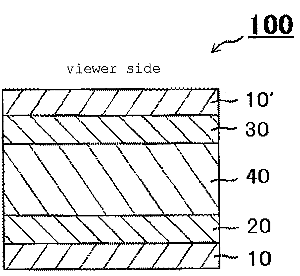
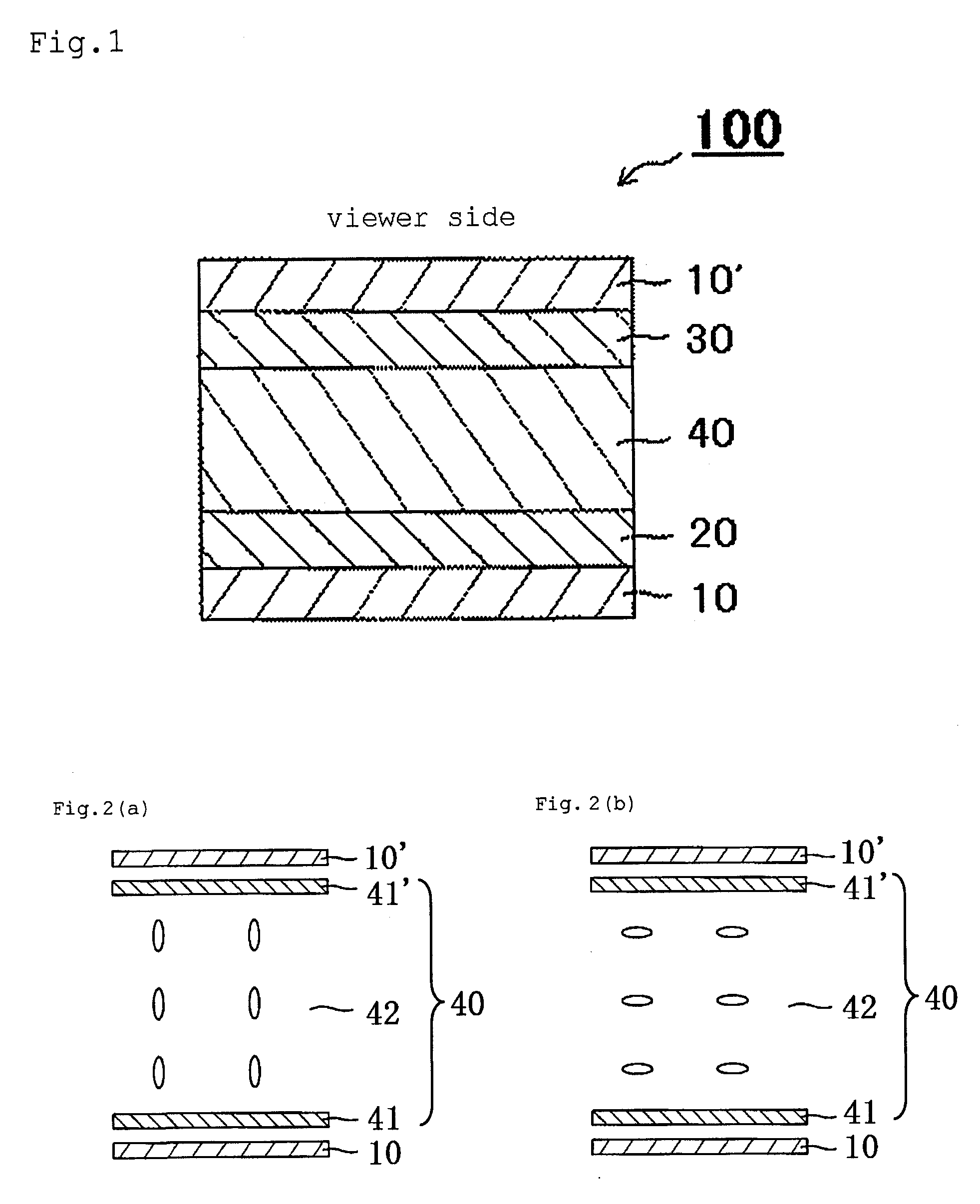
[0099]A VA-mode liquid crystal cell mounted on Play Station Portable (PSP) (trade name) manufactured by Sony Corporation was used. The thickness direction retardation Rthc of the liquid crystal cell was 320 nm.

[0100](Production of Polarizing Plate)

[0101]A commercially-available polyvinyl alcohol film (manufactured by Kurary Co., Ltd.) was dyed in an aqueous solution containing iodine, and uniaxially stretched by 6 times between rolls having different velocities in an aqueous solution containing boric acid to thereby obtain a polarizer. Triacetylcellulose films (thickness: 40 μm, KC4UYW (tradename) manufactured by Konica Minolta Opto, Inc.), as protective films, were attached on both surfaces of the polarizer with a polyvinyl alcohol-based adhesive (thickness: 0.1 μm), whereby a polarizing plate was obtained. The in-plane retardation Re (550) of the protective film was 0.9 nm. Re (550) represents a value measured with light having a wavelength of 550 nm at 23° C.

[0...

example 2

[0111]A liquid crystal panel was produced in the same way as in Example 1 except that the stretching ratio of the film was set to be 1.75 times when producing the first and second optical compensation layers. The first and second optical compensation layers each had a refractive index ellipsoid of nx>ny>nz, an in-plane retardation Re of 140 nm, a thickness direction retardation Rth of 91 nm, and an Nz coefficient of 1.15.

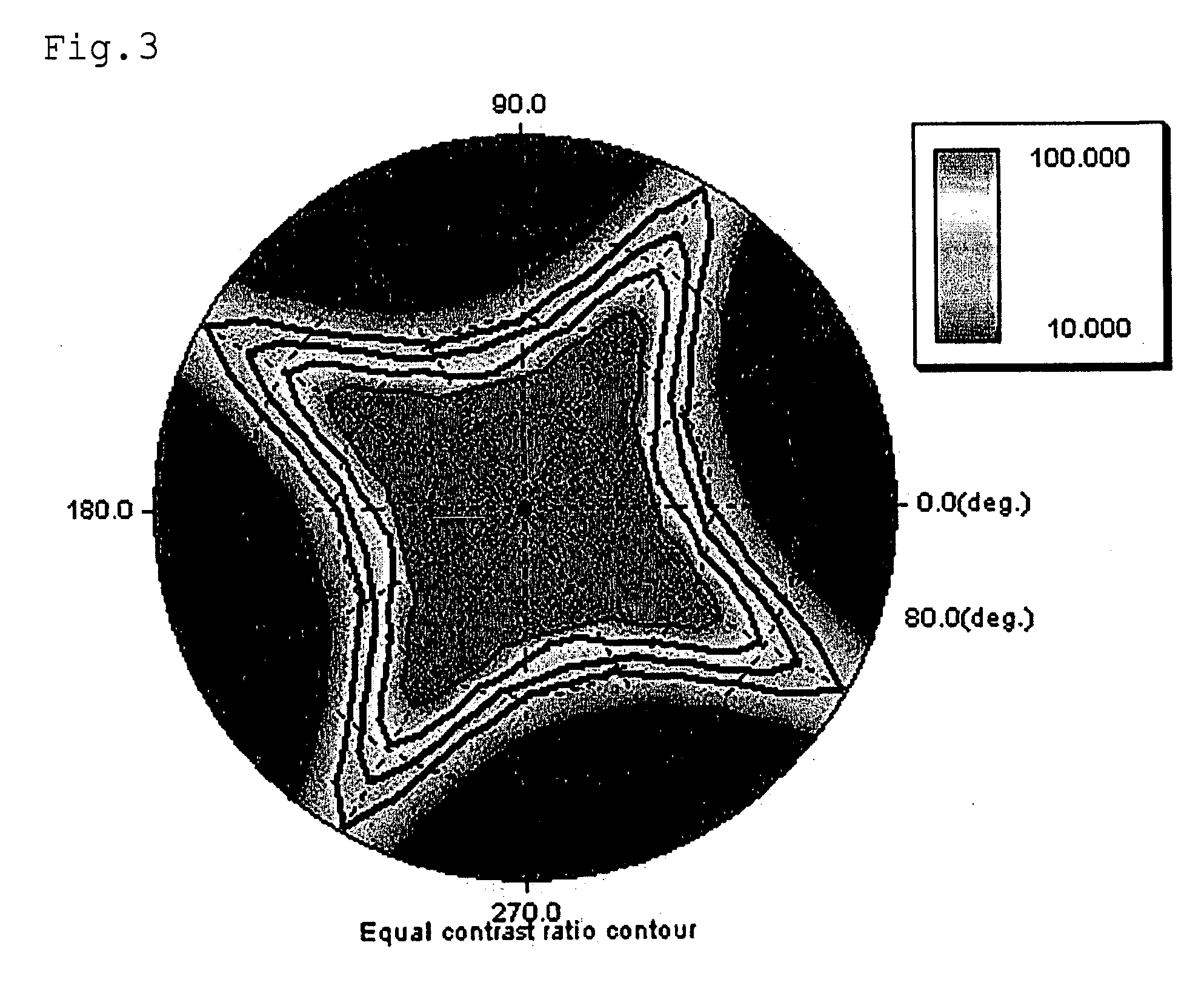
[0112]A computer simulation was conducted regarding the viewing angle dependence of a contrast of a liquid crystal display apparatus using the obtained liquid crystal panel. FIG. 4 shows the results. Note that the difference between the total thickness direction retardation ΣRth1 to 2 of all the optical compensation layers in the liquid crystal panel and the thickness direction retardation Rthc of the liquid crystal cell was −138 nm.

example 3

[0113]A liquid crystal panel was produced in the same way as in Example 1 except that the stretching ratio of the film was set to be 1.5 times when producing the first and second optical compensation layers. The first and second optical compensation layers each had a refractive index ellipsoid of nx>ny>nz, an in-plane retardation Re of 140 nm, a thickness direction retardation Rth of 112 nm, and an Nz coefficient of 1.3.

[0114]A computer simulation was conducted regarding the viewing angle dependence of a contrast of a liquid crystal display apparatus using the obtained liquid crystal panel. FIG. 5 shows the results. Note that the difference between the total thickness direction retardation ΣRth1 to 2 of all the optical compensation layers in the liquid crystal panel and the thickness direction retardation Rthc of the liquid crystal cell was −96 nm.


PUM


Abstract

A liquid crystal panel of the present invention includes in the following order toward a viewer side: a first polarizer; a first optical compensation layer having a refractive index ellipsoid of nx>ny>nz and an in-plane retardation Re1 of 90 to 300 nm; a liquid crystal cell; a second optical compensation layer having a refractive index ellipsoid of nx>ny>nz and an in-plane retardation Re2 of 90 to 300 nm; and a second polarizer, wherein a total thickness direction retardation ΣRth1 to n of all the optical compensation layers and a thickness direction retardation Rthc of the liquid crystal cell satisfy the following Expression (1):
−160nm<(ΣRth1 to n−Rthc)<50nm  (1).

Description

TECHNICAL FIELD[0001]The present invention relates to a liquid crystal panel and a liquid crystal display apparatus using the same. More specifically, the present invention relates to a liquid crystal panel excellent in the balance between contrast and viewing angle properties, and a liquid crystal display apparatus using the liquid crystal panel.BACKGROUND ART[0002]As a liquid crystal display apparatus of a VA mode, a semi-transmission reflection-type liquid crystal display apparatus has been proposed in addition to a transmission-type liquid crystal display apparatus and a reflection-type liquid crystal display apparatus (for example, see Patent Documents 1 and 2). The semi-transmission reflection-type liquid crystal display apparatus enables a display to be recognized visually by using ambient light in a light place in the same way as in the reflection-type liquid crystal display apparatus, and using an internal light source such as a backlight in a dark place. In other words, th...

Claims


Application Information

Patent Timeline
IPC IPC(8): G02F1/13363
CPCG02F1/13363G02F2413/12G02F2413/02G02F2202/40G02F1/1335
Inventor SHUTOU, SHUNSUKEBITOU, MASATOISHIHARA, YOUJI
Owner NITTO DENKO CORP
Why Eureka
Try Eureka