Image forming apparatus having a cleaning member configured to clean a transparent member of an optical device
a technology of optical devices and cleaning members, which is applied in the direction of electrographic process apparatus, printing, instruments, etc., can solve the problems of difficult to clean the cover glass thoroughly, the image forming apparatus is cluttered, and the configuration is complex, so as to achieve the effect of being cleaned efficiently
- Summary
- Abstract
- Description
- Claims
- Application Information
AI Technical Summary
Benefits of technology
Problems solved by technology
Method used
Image
Examples
first embodiment
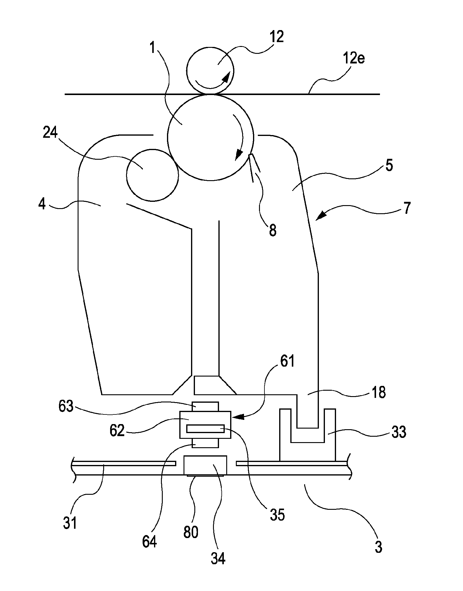
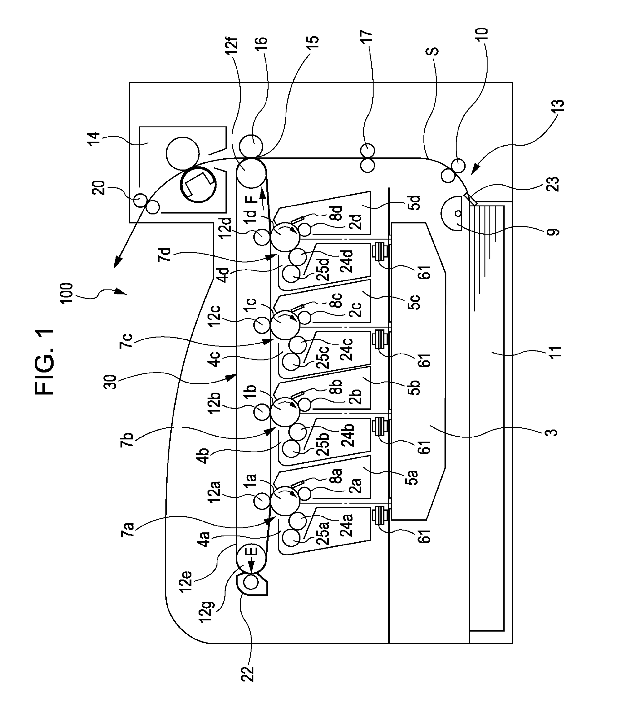
[0038]FIG. 1 is a longitudinal cross-sectional view showing the overall configuration of a color laser printer 100, functioning as an image forming apparatus, according to the present invention. The overall configuration of the image forming apparatus, i.e., the color laser printer 100, will now be described.
Overall Configuration of Image Forming Apparatus
[0039]Referring to FIG. 1, the color laser printer 100 has four process cartridges 7 (7a, 7b, 7c, and 7d), functioning as a first to fourth image forming units. The process cartridges 7 form images in respective colors of yellow, magenta, cyan, and black, and all have the same configuration with different colors of toner. Therefore, reference characters a, b, c, and d added to reference numerals denoting elements shown in FIG. 1 in correspondence with the process cartridges 7 for yellow, magenta, cyan, and black are omitted in the following description unless those elements need to be distinguished from each other by their colors.
[...
second embodiment
[0116]Referring to FIG. 14, the printer 100 includes a shading member 70, functioning as a cover, extending in the longitudinal direction of the cover glass 34. The shading member 70 is disposed near the cover glass 34, avoiding the irradiation area. The shading member 70, which is made of a plate member that is bent into a shade-like shape, prevents toner and dust particles D adhering around the cover glass 34 from moving toward and adhering to the cover glass 34. With the shading member 70, the probability of dust particles adhering to the cover glass 34 can be reduced.
[0117]Referring to FIG. 15, when the laser shutter 35 is at the closed position, the range of movement of the cleaning member 61 in the longitudinal direction of the cover glass 34 does not overlap the shading member 70. In contrast, referring to FIG. 16, when the laser shutter 35 is at the open position, the range of movement of the cleaning member 61 in the longitudinal direction of the cover glass 34 partially o...
third embodiment
[0125]FIG. 17 shows a state where the laser shutter 35 is at the closed position, blocking the optical path of the laser light. FIG. 18 shows a state where the laser shutter 35 is at the open position, without blocking the optical path of the laser light. Referring to FIGS. 17 and 18, the configuration includes a hook 39F, functioning as the locking member, integrally provided at an end of the swivel arm 39, which is included in the link mechanism and provided at an end of the laser shutter 35 in the rear of the main body. When the swivel arm 39 swivels such that the laser shutter 35 is moved to the open position, the hook 39F locks the cleaning member 61.
[0126]Specifically, referring to FIG. 17, when the laser shutter 35 is at the closed position directly above the cover glass 34, the hook 39F is open. When the front door 26 is closed and the laser shutter 35 is moved to the open position, as shown in FIG. 18, where the laser shutter 35 is retracted from the position directly abov...
PUM
 Abstract
Description
Claims
Application Information
 - R&D
- Intellectual Property
- Life Sciences
- Materials
- Tech Scout
- Unparalleled Data Quality
- Higher Quality Content
- 60% Fewer Hallucinations
Browse by: Latest US Patents, China's latest patents, Technical Efficacy Thesaurus, Application Domain, Technology Topic, Popular Technical Reports.
© 2025 PatSnap. All rights reserved.Legal|Privacy policy|Modern Slavery Act Transparency Statement|Sitemap|About US| Contact US: help@patsnap.com


