This helps you quickly interpret patents by identifying the three key elements:
Problems solved by technology
Method used
Benefits of technology
Benefits of technology
[0006]An object of the present invention is to improve the capture rate of a target and the like such as antigen and antibody in a sample, and to uniformize the concentration of substance existing in a solution regardless of the position of a reaction field.
[0040]The rotation direction is adjusted when the mixing is carried out so that the liquid mixture does not leak from the microchannel to outside. In this way, the solution in the mixing chamber can be mixed by turning force used for centrifuging and the like.
Problems solved by technology
However, it is difficult to keep the flow rate constant by pumping a fluid regardless of the position of a channel.
As a result, an antigen and antibody in the solution cannot securely be captured, thus the contact time of the solution such as a sample with the microparticles is varied depending on the position of the reaction field 103, which results in an ununiform concentration of reactant produced by an antigen-antibody reaction in the reaction field 103.
This makes it difficult to partially extract the reaction solution produced in the reaction field and to use it for a subsequent treatment.
For this reason, it is difficult to reduce the amount of sample and reagent in each part subsequent to the reaction field, such as a detection part and a mixing chamber, thus a problem whereby it is difficult to reduce the size of the microchip itself exists.
Method used
Image
Click on the blue label to locate the original text in one second.
Reading with bidirectional positioning of images and text.
Examples
first embodiment
(1) Overall Configuration of Microchip
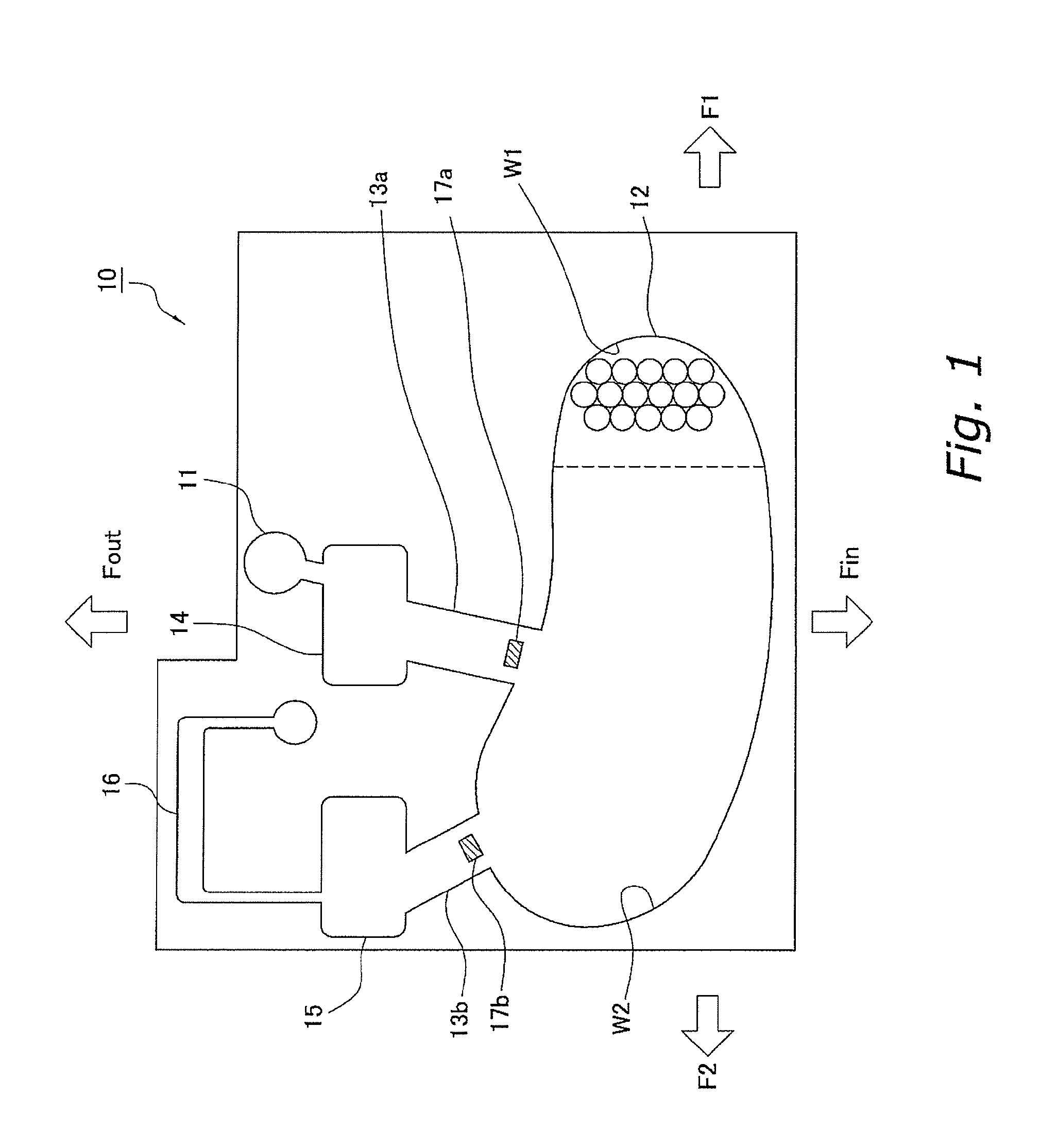
[0050]FIG. 1 is a plan view of a microchip according to a first embodiment. The microchip of the present invention is a microchip based on an assumption that it does not use a pump but uses centrifugal force for moving a solution in a process of mixing a substance, that recognizes a target in a sample, and microparticles.
[0051]A microchip 10 in FIG. 1 has the following elements.
(a) Sample Introduction Part
[0052]A sample introduction part 11 introduces a sample into the microchip 10 from outside. The sample introduction part 11 may also have a function for temporarily holding the introduced sample.
[0053]A mixing chamber 12 holds a granular carrier to which a recognition substance is immobilized (hereinafter referred to as microparticles) or a granular carrier before a recognition substance is immobilized thereto in a way that they can flow. The mixing chamber 12 is a space in which at least the sample and the microparticles are ...
experimental example
[0086]The microchip 10 according to the present invention was prepared, and an experiment was conducted using the prepared microchip 10. FIG. 5 shows photographs showing an experimental example of the microchip 10 of the present invention. In this experiment, Chitopearl was used as a granular carrier, an anti-idiotype antibody as a recognition substance, CRP as a target, and a solution containing CRP which was adjusted with PBS as a sample containing the target. The amount of the sample solution was 12 μL, and the amount of Chitopearl was 10 μL.
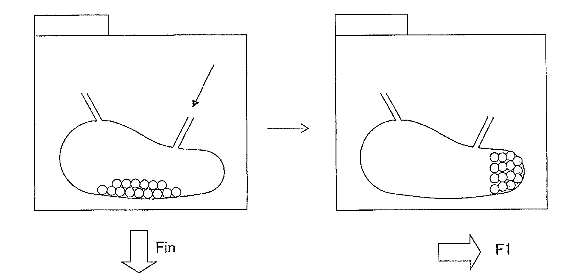
[0087]FIG. 5A shows a stage where the microchip 10 was rotated in the rotation direction that causes centrifugal force Fin in the direction shown with the arrow in the figure, and the sample was introduced into the mixing chamber 12. At this stage, microparticles positioned on the upper wall side in the figure were reacted with the target among the microparticles.
[0088]FIGS. 5B, 5C and 5D each shows a state after the microchip 10 was rotated ...
second embodiment
[0091]FIG. 6 is a plan view of a microchip 20 according to a second embodiment. The same reference numerals are assigned to the elements that have the same functions as the microchip 10 described in the first embodiment. In the microchip 20 of the present embodiment, the diameter of the microchannels 13 is formed smaller than the diameter of the microparticles in the mixing chamber 12 at the connection parts to the mixing chamber 12. In this way, the microparticles in the mixing chamber 12 are prevented from flowing out to the microchannels 13 no matter from which direction centrifugal force is applied to the microchip 10. Other configurations of the microchip 20, a treatment process using the microchip 20, a method for using the microchip 20 and the like in the present embodiment are the same as those of the first embodiment described earlier.
PUM
Abstract
The capture rate of a target such as antigen and antibody in a sample is improved and the concentration of reaction product of a recognition substance is uniformized regardless of the position of a reaction field. By contacting microparticles and the sample using centrifugal force, the contact time of the target and the recognition substance is equalized regardless of the position in mixing chamber The microparticles and the sample are mixed evenly in the mixing chamber by changing the rotation direction and the concentration of reactant in a liquid mixture is uniform regardless of the position of the mixing chamber. When the liquid mixture having a uniform concentration is obtained, it is enough to extract a part of the liquid mixture and use the same for a process subsequent to a mixing process without the need of using all the liquid mixture.
Description
TECHNICAL FIELD[0001]The present invention relates to a method for using a microchip, a microchannel and a microchip. It also relates to a microchannel used for separating, mixing and detecting a biomaterial substance, a method for using a microchip having the same, a microchannel and a microchip.BACKGROUND ART[0002]Patent Document 1 discloses an immuno analyzer that aims to enable an easy and high-precision immuno analysis in a short time with a small quantity of sample. FIG. 7 is a perspective view showing a configuration of this immuno analyzer. A solution introduced from an introduction part 105 of an immuno analyzer 101 reacts with microparticles 102 immobilized to a reaction field 103.[Patent Document 1] Japanese Patent Laid-open No. 2001-004628SUMMARY OF THE INVENTION[0003]However, it can be assumed that a pump is used for contacting the solution with the microparticles 102 for the immuno analyzer of Patent Document 1. It is because this immuno analyzer 101 does not have a co...
Claims
Application Information
Patent Timeline
Application Date:The date an application was filed.
Publication Date:The date a patent or application was officially published.
First Publication Date:The earliest publication date of a patent with the same application number.
Issue Date:Publication date of the patent grant document.
PCT Entry Date:The Entry date of PCT National Phase.
Estimated Expiry Date:The statutory expiry date of a patent right according to the Patent Law, and it is the longest term of protection that the patent right can achieve without the termination of the patent right due to other reasons(Term extension factor has been taken into account ).
Invalid Date:Actual expiry date is based on effective date or publication date of legal transaction data of invalid patent.

