
Endovenous valve transfer stent

Inactive Publication Date: 2009-10-29
ALL VASCULAR PTY LTD
View PDF0 Cites 107 Cited by
  • Summary
  • Abstract
  • Description
  • Claims
  • Application Information

AI Technical Summary

Benefits of technology

[0005]Further objects of the invention are to provide an exo-stent with a variable diameter i.e. placed circumferentially around the valve containing vein segment usually in the axilla or contralateral profunda vein. The anastomosis to the stent would need to be fluid sealed to prevent endoleak. The stent itself would need to have minimal blood interface to minimise thrombogenicity and, in order to prevent long term dilatation of the venous valve ring, the final stent diameter would need to be fixed to prevent long term dilatation.

Problems solved by technology

Chronic venous insufficiency imposes an enormous clinical and financial burden on the community with current treatment modalities being unsatisfactory.
However, these procedures require considerable surgical skill, and may be associated with potentially serious complications, specifically, deep venous thrombosis and pulmonary embolism, and so are not commonly performed.
Additionally, there are problems related to valve ring dilatation and subsequent incompetence in the long term.

Method used


Image

  • Endovenous valve transfer stent
  • Endovenous valve transfer stent
  • Endovenous valve transfer stent

Examples


example 1

[0031]Subjects. Sixteen sheep weighing between forty-five to fifty kilograms were used in the study. The investigative protocol was approved by the Animal Ethics Committee of the Northern Sydney Central Coast Health Service.

[0032]Stent Materials. NITINOL (nickel titanium alloy) was chosen to take advantage of its super-elastic properties including its self-expansion capability and a very low mass expansion ratio. The lower profile allows minimisation of the delivery system. NITINOL has known and reproducible bio-compatibility. The fatigue deformity strength and electromagnetic profiles and stress strain characteristics are well documented and easy to test. NITINOL itself is easy to shape and it also has shape memory characteristics which allow crimping capability when cooled.

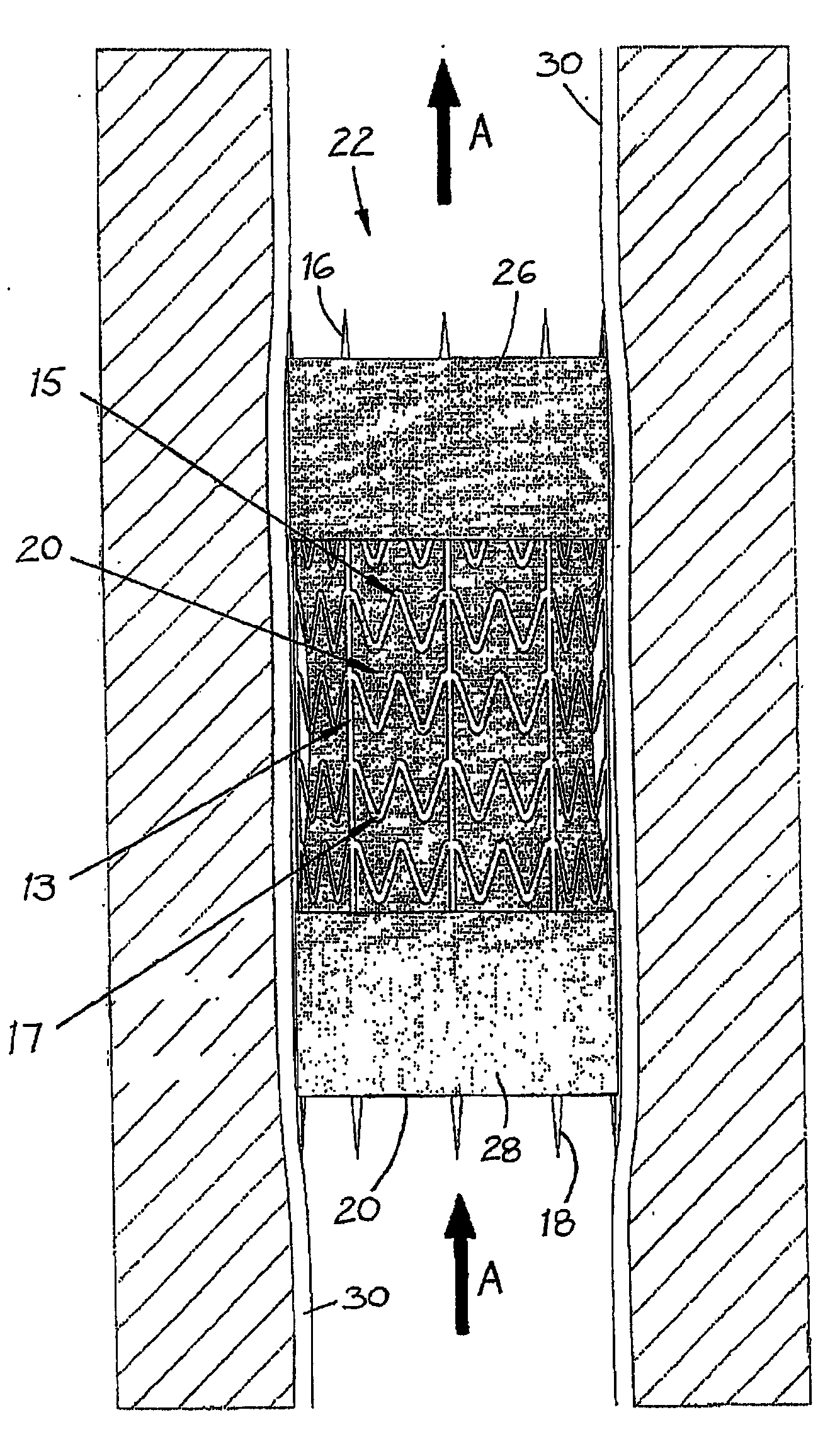
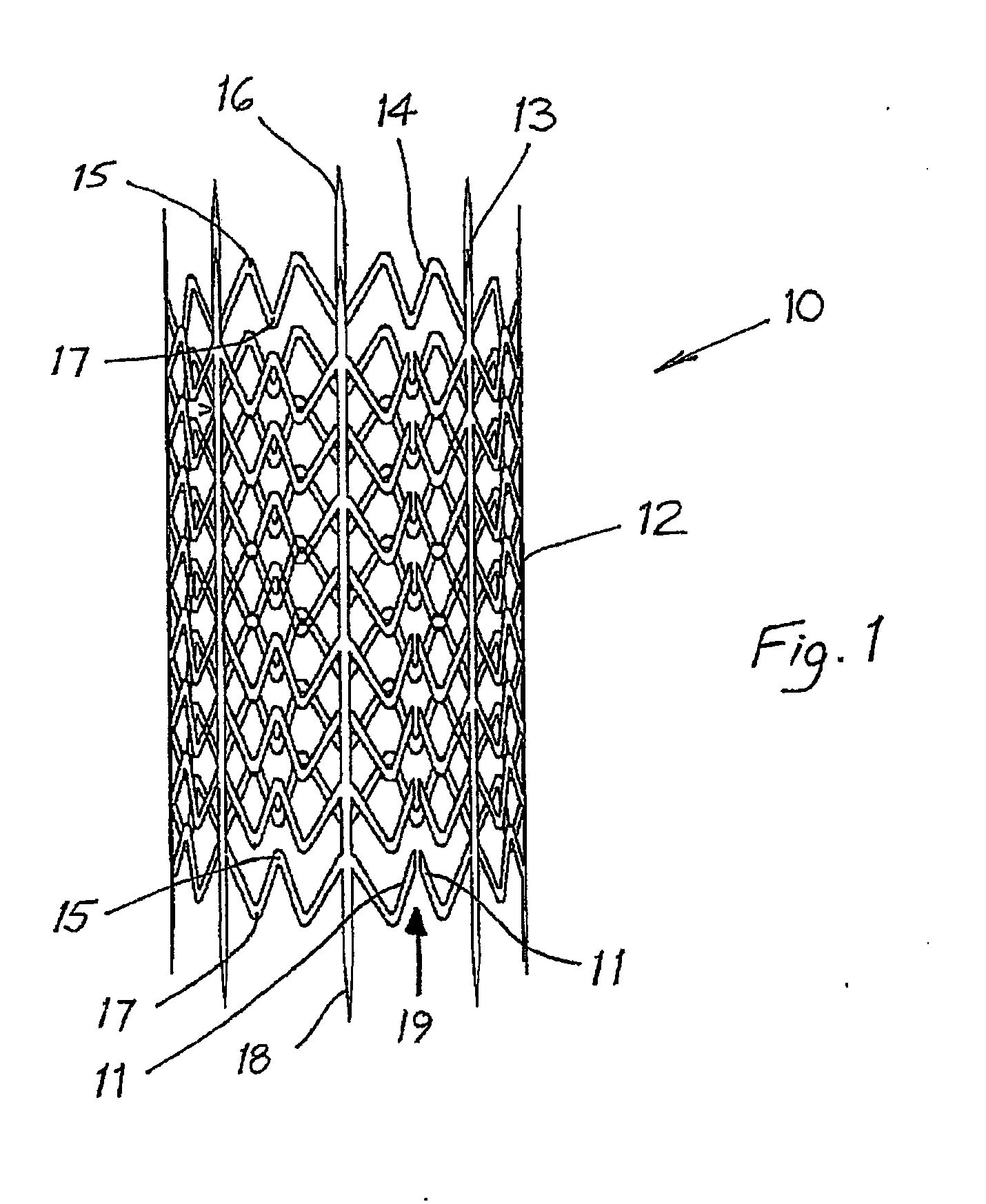
[0033]Stent Design. A preferred endovenous valve transfer stent (EVTS) is shown in FIG. 1.

[0034]1. To maximise wall fixation, the following EVTS structural features were included:[0035]a. Spikes (3 mm in length)...

example 2

[0062]Case Report. A sixty-three year old man presented with a thirty-four year history of virtually continuous right lower limb chronic venous ulceration following an extensive DVT related to severe trauma. Treatment over the years consisted of continuous graduated compression, multiple failed skin grafts and a high ligation and stripping of the great saphenous vein plus other ablative venous procedures. He had multiple infective problems including multiple admissions to hospital for recurrent septicaemia. At the time of the EVTS procedure his ulcer area was 45 cm2. A Venogram and duplex ultrasound of his left upper limb both demonstrated competent valves with internal diameters (ID) of 9 mm and 7 mm. Descending venography showed Grade IV reflux that extended from the femoral veins down to and including the infrapopliteal systems. Extensive post-phlebitic intraluminal changes were noted including vein wall thickening and irregularity. The popliteal vein ID varied between 8-10 mm.

[0...


PUM


Abstract

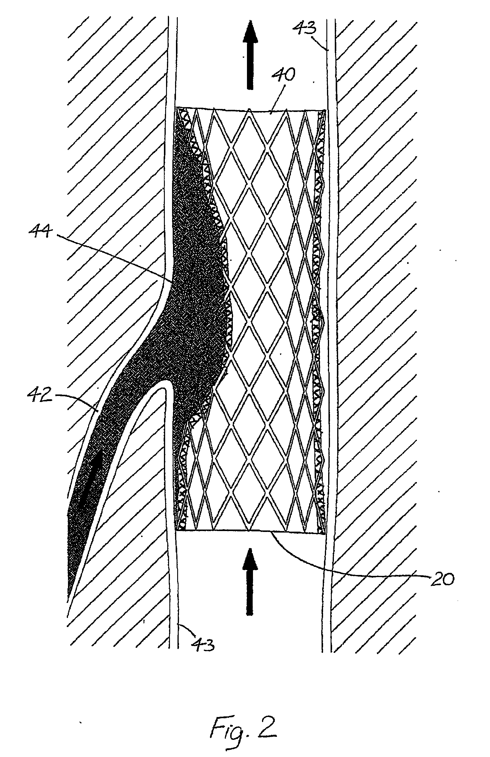
An endovenous valve transfer stent (10) has an elongated tubular open-work body (12) having a network of longitudinally extending ribs (13) interconnected by laterally extending zigzag struts (14). The struts define a plurality of barbs (15, 17) in opposing longitudinal directions. The body (12) has a first end and a second end, and includes a longitudinal cut through the struts (14) from the first end to the second end. A seam (19) is defined between adjacent cut ends of each strut. The body (12) is adapted, in use, to vary in its diameter to receive a donor valve containing vein segment (20) longitudinally therethrough.

Description

FIELD OF INVENTION[0001]This invention relates to surgical stents and more particularly to an endovenous valve transfer stent for transferring a donor valve containing vein segment to a recipient vein having a defective or absent venous valve. More particularly, the present invention relates to an endovenous valve transfer stent for treatment of chronic venous disease.BACKGROUND OF THE INVENTION[0002]Chronic venous insufficiency imposes an enormous clinical and financial burden on the community with current treatment modalities being unsatisfactory. The syndrome relates to venous valve dysfunction leading to venous reflux, outflow congestion and venous hypertension. It is well known that this may lead to varicose veins, chronic venous ulcers and other related conditions in the long term.[0003]Venous valves repaired directly or by venous valve transposition have produced encouraging results in the short and long term. However, these procedures require considerable surgical skill, and...

Claims


Application Information

Patent Timeline
IPC IPC(8): A61F2/06A61F2/82
CPCA61F2/2409A61F2/2418A61F2/2475A61F2/91A61F2/915A61F2002/825A61F2230/0054A61F2002/8486A61F2002/91533A61F2002/9155A61F2002/91575A61F2220/0008A61F2220/0016A61F2002/8483
Inventor LANE, RODNEY JAMES
Owner ALL VASCULAR PTY LTD
Learn More