
Method and apparatus for manufacturing ultralow-resistance current sensors

a technology of resistance current and manufacturing method, which is applied in the direction of resistor housing/enclosement/embedding, manufacturing tools, instruments, etc., can solve the problems of high cost, difficult to achieve deep grooves, and microlithography can produce only current sensors of sizes larger than 1206

Active Publication Date: 2009-11-05
PAN JEN HUAN
View PDF5 Cites 19 Cited by
  • Summary
  • Abstract
  • Description
  • Claims
  • Application Information

AI Technical Summary

Benefits of technology

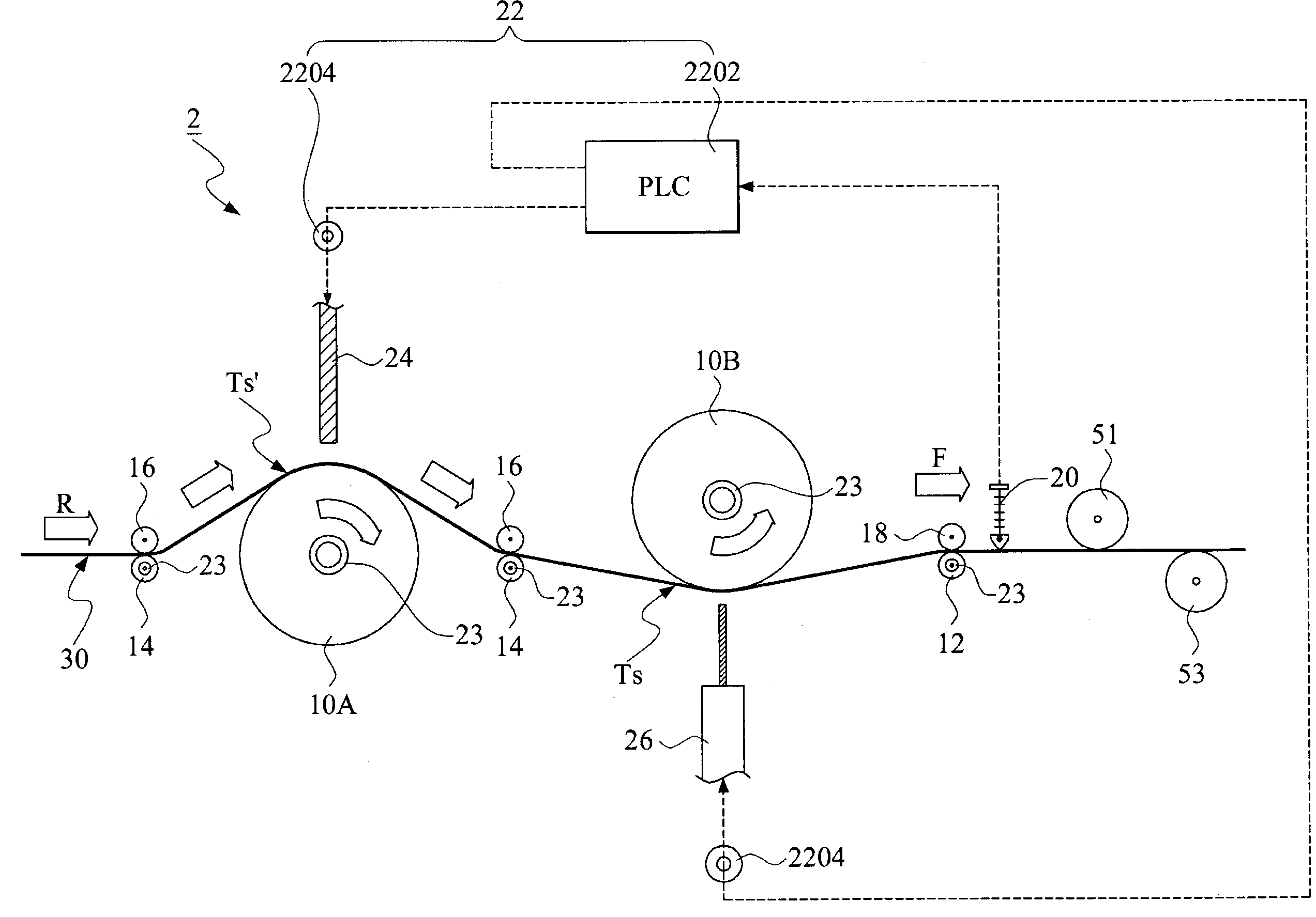
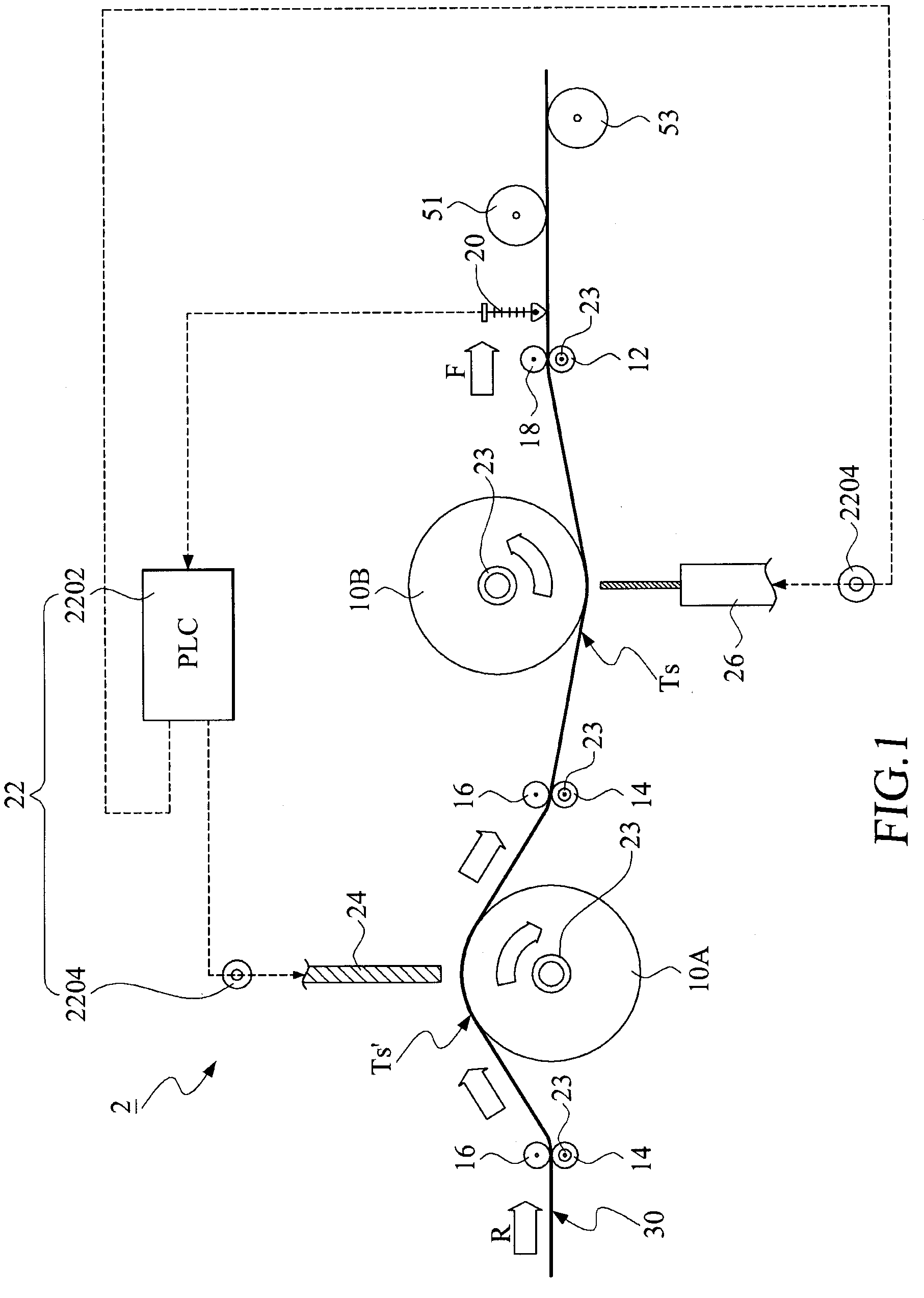
[0008]It is an object of the present invention to provide a method and an apparatus for manufacturing ultralow-resistance current sensors in accordance with a metal manufacturing process, which can better maintain metallic characteristics during the production process and can yield products of sizes substantially smaller than that achieved by the aforesaid punching process or microlithography.

Problems solved by technology

However, microlithography can produce only current sensors of sizes larger than 1206.
Cost is high, and deep grooves are difficult to achieve.
The process is also time-consuming and liable to environmental protection issues.
Further, the current sensors manufactured by punching are restricted to sizes larger than 4518.
It is therefore not easy to miniaturize electronic elements by metal manufacturing processes to meet the requirement of portable electronic devices.
However, this process changes metallic configurations, deteriorates metallic characteristics, and results in significantly elevated resistance in response to in creasing ambient temperature.
Thus, although the thin film process can miniaturize the ultralow-resistance current sensor, it yields products with high measurement errors, which is causes for major concerns; in particular, for the high-end products of portable electronic devices.

Method used


Image

  • Method and apparatus for manufacturing ultralow-resistance current sensors
  • Method and apparatus for manufacturing ultralow-resistance current sensors
  • Method and apparatus for manufacturing ultralow-resistance current sensors

Examples


Embodiment Construction

[0025]The invention disclosed herein is directed to a method and an apparatus for manufacturing ultralow-resistance current sensors. In the following description, numerous details are set forth in order to provide a thorough understanding of the present invention. It will be appreciated by one skilled in the art that variations of these specific details are possible while still able to achieve the results of the present invention. In other instance, well-known components are not described in detail in order not to unnecessarily obscure the present invention.

[0026]The following detailed description is of the best known modes of realizing the invention. This description is not to be taken in a limiting sense, but is made merely for the purpose of illustrating general principles of embodiments of the invention. The scope of the invention is best defined by the appended claims.

[0027]In the present invention, the size of the ultralow-resistance current sensor is in the range between 0402...


PUM

PropertyMeasurementUnit
Thicknessaaaaaaaaaa
Electrical resistanceaaaaaaaaaa
Sizeaaaaaaaaaa

Abstract

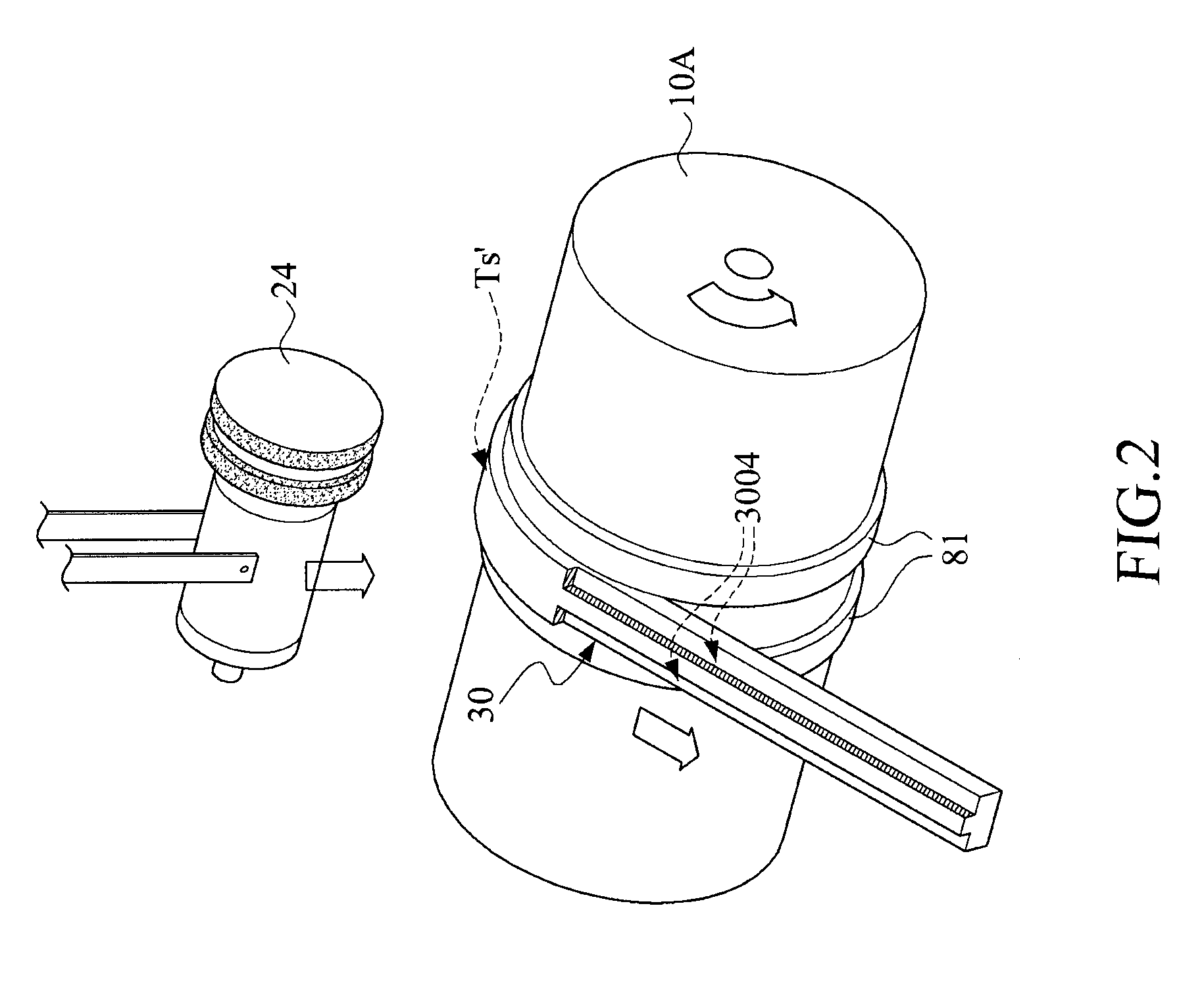
A method for manufacturing ultralow-resistance current sensors of size 0402 to 4518 of IEEE specifications includes the steps of: a raw metallic strip being pressed to roll over a first tension roller, a cutting tool over the first tension roller being fed to cut the raw metallic strip so as to form a deep groove thereof along the moving metallic strip, an insulating material being filled into and along the deep groove so as to form an lengthwise insulating portion of the metallic strip, and the metallic strip with the insulating portion being segmented into a plurality of ultralow-resistance current sensors.

Description

[0001]This application claims the benefit of Taiwan Patent Application Serial No. 097116528, filed May 5, 2008, the subject matter of which is incorporated herein by reference.BACKGROUND OF THE INVENTION[0002](1) Field of the Invention[0003]The present invention relates to a method for producing ultralow-resistance current sensors and an apparatus for processing the same.[0004](2) Description of the Prior Art[0005]The ultralow-resistance current sensor, also called the current-sensing resistor, a kind of current-induced electronic elements whose resistances are ranged between 0.1Ω and 0.0005Ω, is usually used for monitoring working voltages of various circuit designs. For example, the ultralow-resistance current sensor can be used as a recharge indicator for batteries, or a monitor for working currents or working voltages. In particular, the ultralow-resistance current sensor is now playing an important role in energy-saving and carbon-reduction design.[0006]Current sensors can be m...

Claims


Application Information

Patent Timeline
IPC IPC(8): B21B1/00H01C17/00
CPCG01R1/203H01C17/02H01C17/065Y10T29/49007Y10T29/49089Y10T29/49641Y10T29/49082G01R3/00
Inventor PAN, JEN-HUAN
Owner PAN JEN HUAN
Learn More