

Mobile hydraulic workover rig
a technology of hydraulic workover rig and mobile rig, which is applied in the direction of drilling rods, drilling pipes, drilling/well accessories, etc., to achieve the effect of reliable and efficient manner
Inactive Publication Date: 2009-11-05
RODGERS TECH
View PDF12 Cites 37 Cited by
- Summary
- Abstract
- Description
- Claims
- Application Information
AI Technical Summary
Benefits of technology
[0006]It is therefore an object to provide for a novel and improved rig which is conformable for use in servicing wells which are located on land or offshore in a reliable and efficient manner.
[0007]Another object is to provide for a novel and improved portable workover rig which is completely fluid-actuated, is extremely stable and does not require the use of guidewires or cables to anchor to the ground.
[0008]A further object is to provide for a novel and improved workover rig which includes a hollow base structure containing the necessary pumps and reservoirs for hydraulic actuation while at the same time greatly stabilizing the entire structure; and further wherein the entire rig including the derrick and base structure can be advanced between wells without disassembly of any of the rig structure.
Problems solved by technology
It has also been proposed to utilize skids without disassembling the structure but has required some disassembly of the derrick and is undesirable from a number of standpoints including but not limited to the time and cost of installation each time that the rig has to be moved; and in the past such installation has involved the utilization of cables or guidewires anchored in the ground to stabilize the derrick.
Method used
View moreImage
Smart ImageViewing Examples

Examples
second embodiment
DETAILED DESCRIPTION OF SECOND EMBODIMENT
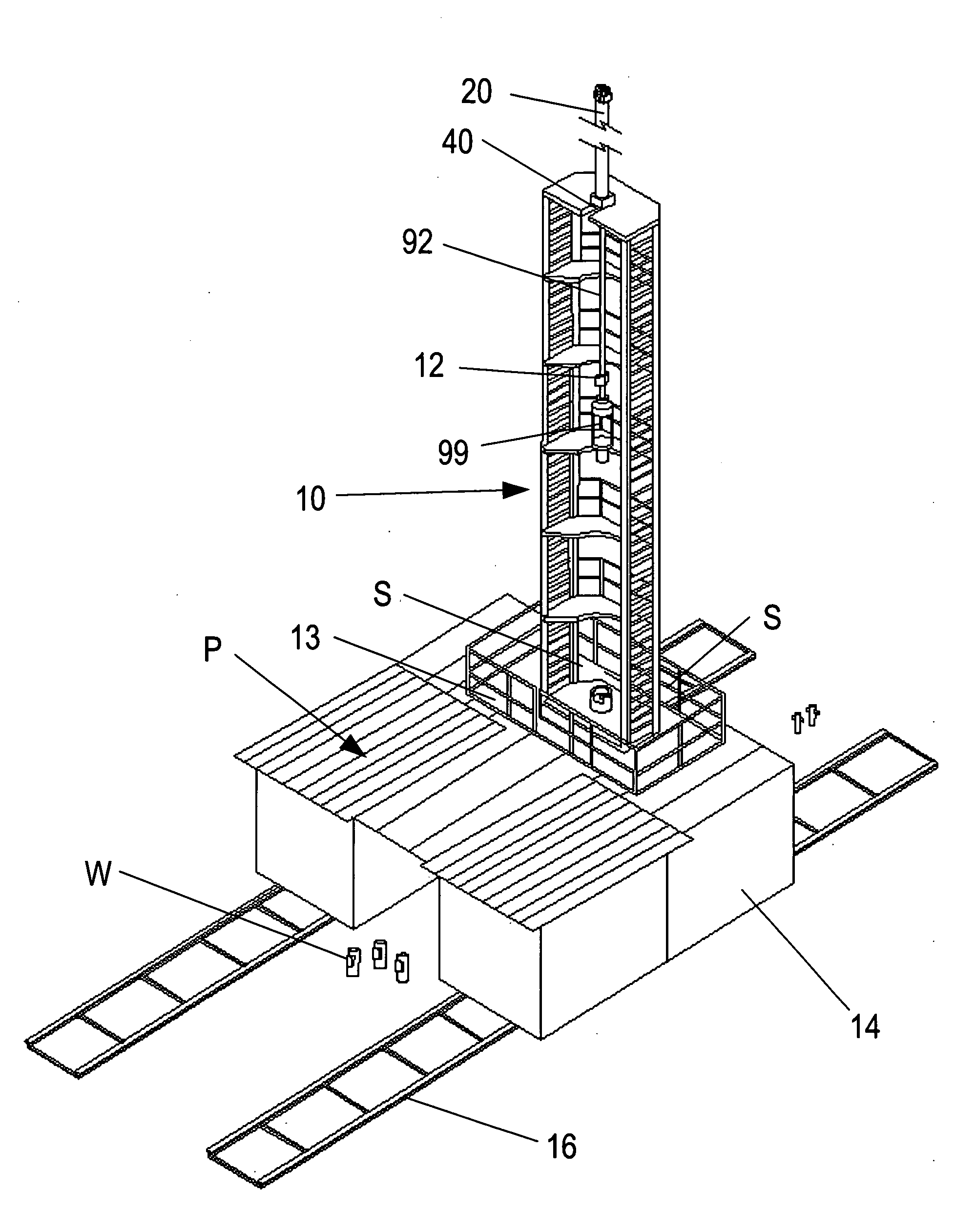
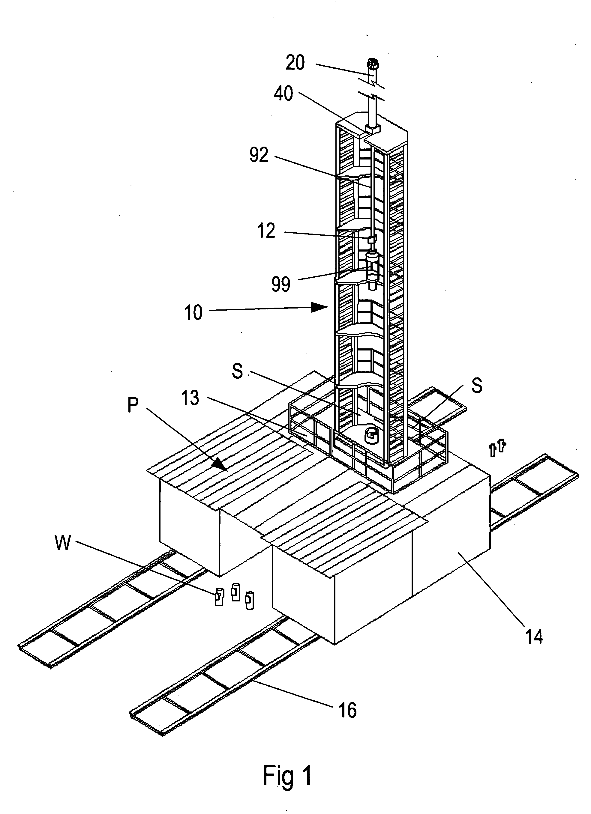
[0052]An offshore drilling 10′ is illustrated in FIG. 26 wherein like parts are correspondingly enumerated with prime numerals. Again, the rig 10′ is made up of a derrick 12′ mounted on base housing members or containers, not shown, which can be affixed or mounted on the standard offshore drilling platform, not shown, and therefore can utilize the existing positioning controls on the drilling platform to advance the derrick into position for the workover operation. The work floor 13′ has the same components including the catwalk, grating spacers, and pipe racks as described in the first embodiment.
Login to View More PUM
 Abstract
A portable hydraulic rig for workover, drilling or other operations on existing wells in which the rig has a derrick elevated on a base structure comprised of containers for equipment used in association with drilling or workover activities, a work platform including pipe rack sections for storing a plurality of pipes, the derrick being open-sided with a power cylinder at its upper end for lifting and lowering pipe sections away from and into each well, and hydraulic drive cylinders for advancing the rig between wells without telescoping or pivoting the derrick into a travel position, all of the hydraulic components being controlled from a central control panel on the work platform.
Description
CROSS REFERENCE TO RELATED APPLICATION[0001]The present application is a utility conversion of provisional patent application Ser. No. 61 / 126,011 filed 30 Apr. 2008, for Mobile Hydraulic Workover Rig, by Troy A. Rogers and herein incorporated by reference.BACKGROUND AND FIELD[0002]The following relates to workover and drilling rigs, and more particularly relates to a novel and improved method and apparatus adaptable for use in the servicing and treatment of oil or gas wells.[0003]An important consideration in the design and construction of workover rigs in the servicing and treatment of wells is the ability to move efficiently between wells which are located a short distance from one another, such as, for example, wells in a cluster or in one or more rows in directional drilling operations.[0004]In the past, workover rigs have been so constructed and arranged that the derrick and its substructure must be disassembled to move between each well. It has also been proposed to utilize sk...
Claims
Login to View More Application Information
Patent Timeline
 Patent Type & AuthorityApplications(United States)
IPC IPC(8): E21B15/00E21B19/00E21B31/00E21B19/08
CPCE21B19/00E21B15/003
InventorRODGERS, TROY A.
OwnerRODGERS TECH