Printhead including a looped heater element

a heater element and printhead technology, applied in the field of printheads, to achieve the effect of efficient and reliabl

Inactive Publication Date: 2008-02-28
SILVERBROOK RES PTY LTD +1
View PDF23 Cites 0 Cited by
  • Summary
  • Abstract
  • Description
  • Claims
  • Application Information

AI Technical Summary

Benefits of technology

[0017] It is an object of the present invention to provide an ink ejection nozzle arrangement suitable for incorporation into an inkjet printhead arrangement for the ejection of ink on demand from a nozzle chamber in an efficient and reliable manner.
[0024] By designing the bubble forming chamber with a circular cross section, it has much greater structural strength and rigidity. The circular geometry avoids areas of high stress concentration that are prone to failure. The use of an inherently high strength structure allows it to use less material and have a more compact design which improves the nozzle density of the printhead. This in turn improves the printing resolution.

Problems solved by technology

Each technology may have its own advantages and disadvantages in the areas of cost, speed, quality, reliability, power usage, simplicity of construction operation, durability and consumables.

Method used


Image

  • Printhead including a looped heater element
  • Printhead including a looped heater element
  • Printhead including a looped heater element

Examples


Embodiment Construction

[0062] Thermal Bend Actuator

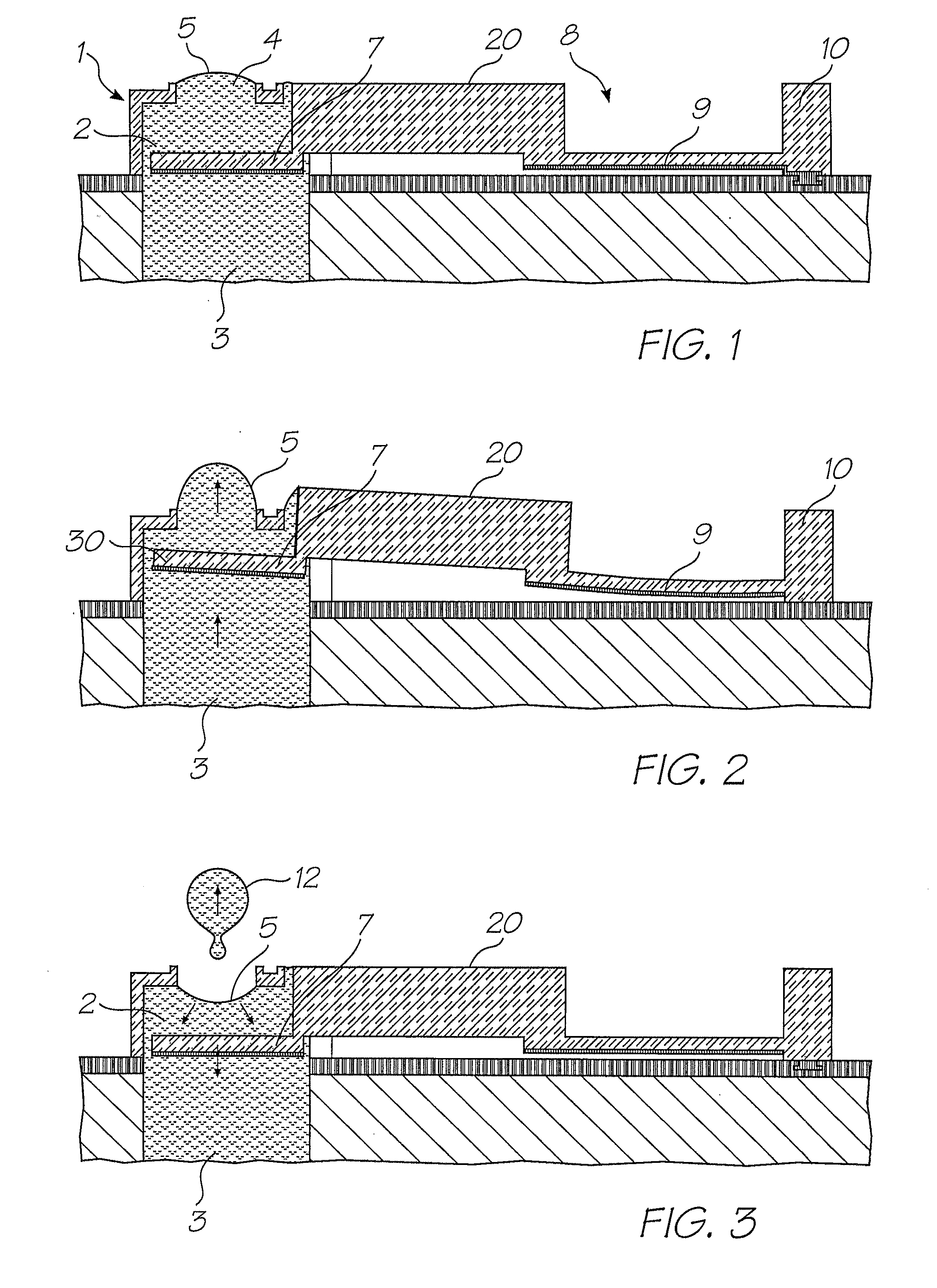
[0063] In an embodiment related to the present invention, there is provided a nozzle arrangement having a nozzle chamber containing ink and a thermal bend actuator connected to a paddle positioned within the chamber. The thermal actuator device is actuated so as to eject ink from the nozzle chamber. The preferred embodiment includes a particular thermal bend actuator which includes a series of tapered portions for providing conductive heating of a conductive trace. The actuator is connected to the paddle via an arm received through a slotted wall of the nozzle chamber. The actuator arm has a mating shape so as to mate substantially with the surfaces of the slot in the nozzle chamber wall.

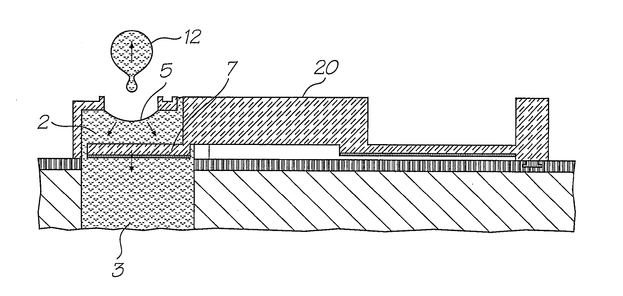
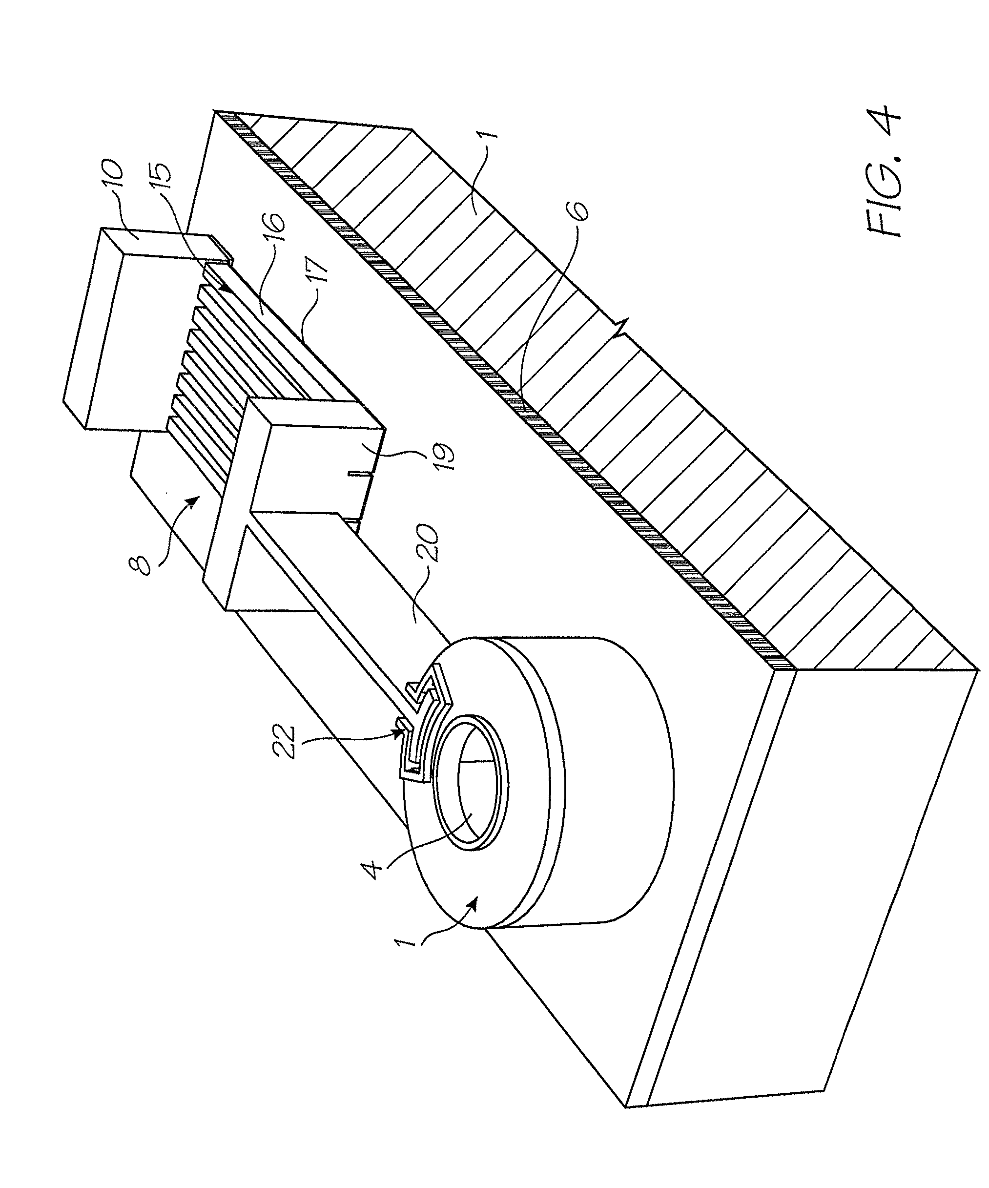
[0064] Turning initially to FIG. 1-3, there is provided schematic illustrations of the basic operation of a nozzle arrangement of this embodiment. A nozzle chamber 1 is provided filled with ink 2 by means of an ink inlet channel 3 which can be etched through a wafer sub...


PUM


Abstract

An ink jet printhead comprising: a plurality of nozzles; a bubble forming chamber corresponding to each of the nozzles respectively, the bubble forming chambers adapted to contain a bubble forming liquid; and at least one looped heater element disposed in each of the bubble forming chambers respectively, the heater elements configured for thermal contact with the bubble forming liquid; wherein heating of the looped heater element to a temperature above the boiling point of the bubble forming liquid forms a gas bubble that causes the ejection of a drop of an ejectable liquid through the nozzle corresponding to that heater element.

Description

CROSS REFERENCES TO RELATED APPLICATIONS [0001] The present application is a continuation of U.S. application Ser. No. 10 / 728,790 filed Dec. 8, 2003, which is a continuation in part of U.S. application Ser. No. 10 / 160,273 filed on Jun. 4, 2002, now issued as U.S. Pat. No. 6,746,105, which is a continuation of U.S. application Ser. No. 09 / 112,767 filed on Jul. 10, 1998, now issued as U.S. Pat. No. 6,416,167, all of which are herein incorporated by reference. [0002] The following Australian provisional patent applications are hereby incorporated by cross-reference. For the purposes of location and identification, US patent applications identified by their US patent application serial numbers (USSN) are listed alongside the Australian applications from which the US patent applications claim the right of priority. US PATENT / CROSS-REFERENCEDPATENT APPLICATIONAUSTRALIAN(CLAIMING RIGHTPROVISIONALOF PRIORITY FROMPATENTAUSTRALIAN PROVISIONALDOCKETAPPLICATION NO.APPLICATION)NO.PO79916750901A...

Claims


Application Information

Patent Timeline
Patent Type & Authority Applications(United States)
IPC IPC(8): B41J2/05B41J2/14B41J2/16B41J2/165B41J2/175B41J3/42B41J3/44B41J11/00B41J11/70B41J15/04G06F1/16G06F21/00G06K1/12G06K7/14G06K19/06G06K19/073G07F7/08G07F7/12G11C11/56H04N1/00H04N1/21H04N1/32H04N5/225H04N5/262
CPCB41J2/1412H04N2101/00B41J2/1601B41J2/1623B41J2/1626B41J2/1628B41J2/1629B41J2/1631B41J2/1632B41J2/1635B41J2/1637B41J2/1639B41J2/1642B41J2/1643B41J2/1645B41J2/1646B41J2/1648B41J2/16585B41J2/17513B41J2/17596B41J3/445B41J11/0005B41J11/70B41J15/04B41J2002/041B41J2002/14346B41J2002/14435B41J2002/14475B41J2202/21B42D2035/34B82Y30/00G06F21/79G06F21/86G06F2221/2129G06K1/121G06K7/14G06K7/1417G06K19/06037G11C11/56H04N1/2154H04N5/225H04N5/2628B41J2/14427H04N23/00
Inventor SILVERBROOK, KIA
Owner SILVERBROOK RES PTY LTD
Why Eureka
Try Eureka