Acoustic wave filter apparatus

a filter apparatus and waveguide technology, applied in the field of acoustic wave filter apparatus, can solve the problems of increased insertion loss increased insertion loss, etc., and achieve the effect of reducing insertion loss and preventing deterioration of balancing

Active Publication Date: 2009-11-05
MURATA MFG CO LTD
View PDF4 Cites 19 Cited by
  • Summary
  • Abstract
  • Description
  • Claims
  • Application Information

AI Technical Summary

Benefits of technology

[0010]In view of the current situation of the related art, preferred embodiments of the present invention provide an acoustic wave filter apparatus that includes multiple acoustic wave filter sections each having a balance-unbalance conversion function and a reduced inse

Problems solved by technology

This has caused a problem that the surface acoustic wave filter apparatus is affected by parasitic capacitances, inductances, or resistances of the wiring lines and t

Method used


Image

  • Acoustic wave filter apparatus
  • Acoustic wave filter apparatus
  • Acoustic wave filter apparatus

Examples


Embodiment Construction

[0039]Now, the present invention will be clarified by describing specific preferred embodiments of the present invention with reference to the accompanying drawings.

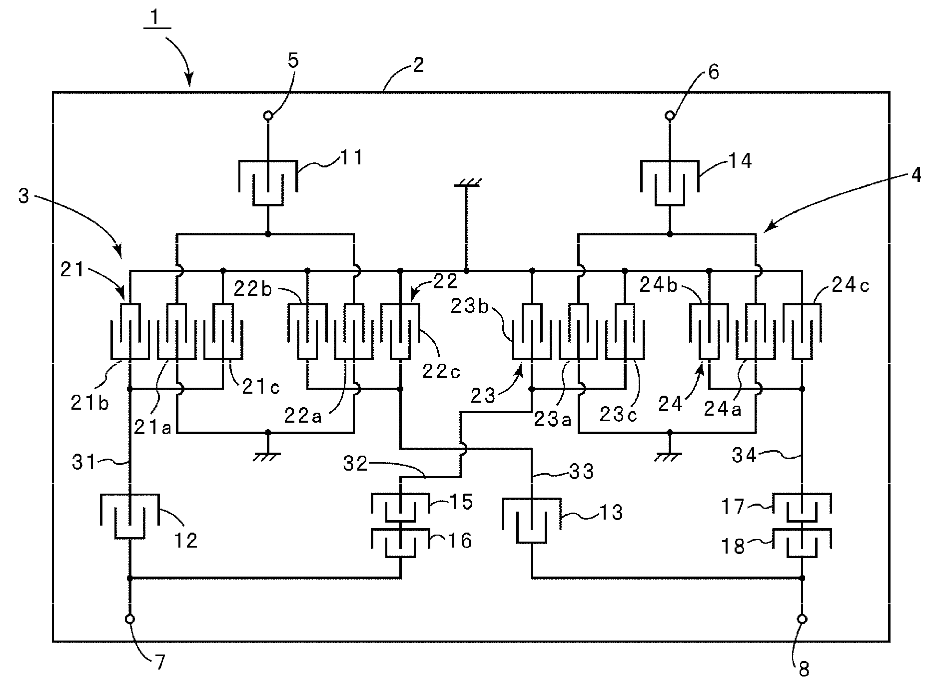
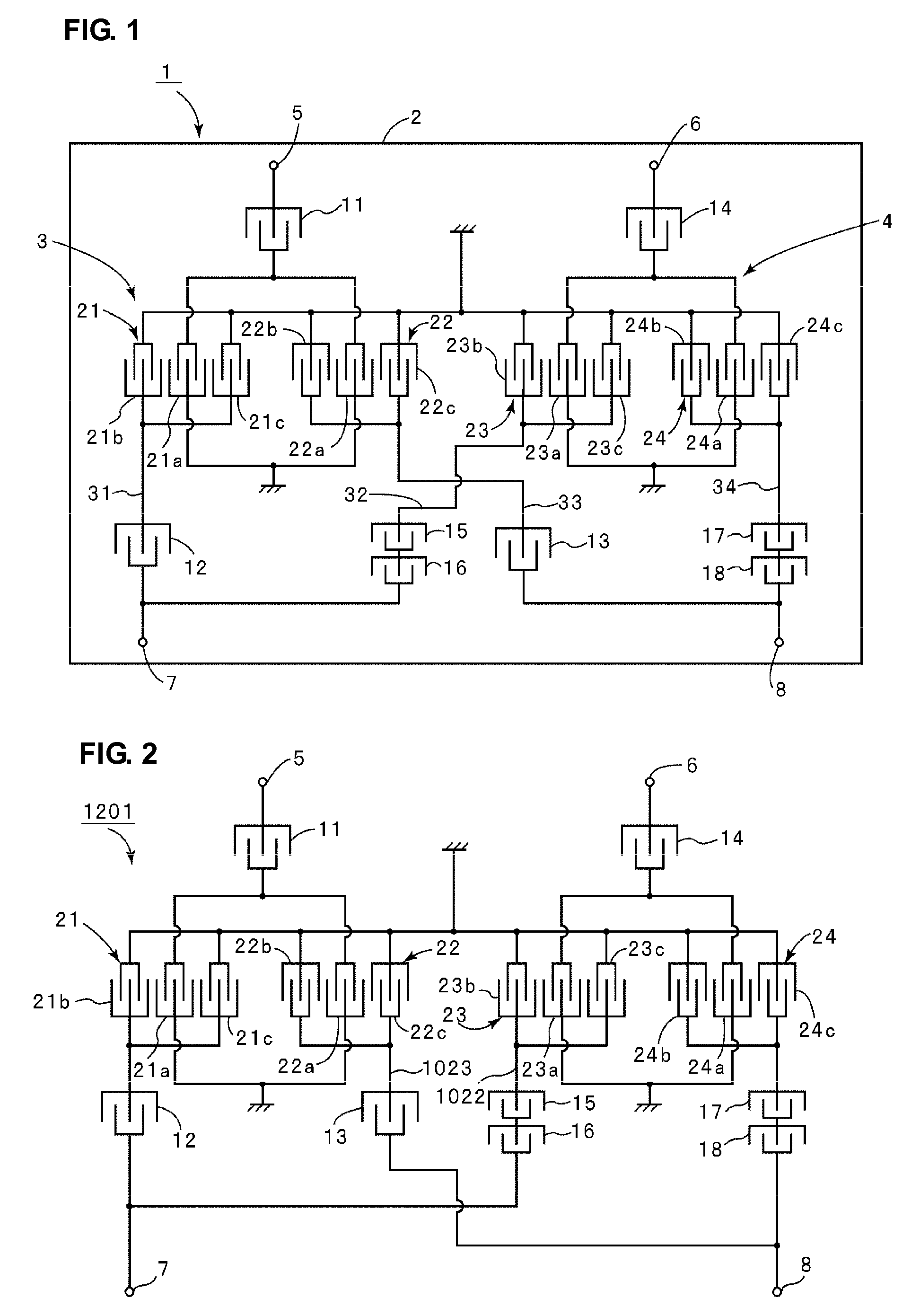
[0040]FIG. 1 is a schematic plan view showing a surface acoustic wave filter apparatus 1 serving as an acoustic wave apparatus according to a first preferred embodiment of the present invention. The surface acoustic wave filter apparatus 1 includes a piezoelectric substrate 2.

[0041]In this preferred embodiment, the piezoelectric substrate 2 is preferably made of 38.5° Y-cut X propagation LiTaO3, for example. Alternatively, the piezoelectric substrate 2 may be made of different piezoelectric monocrystal or piezoelectric ceramic or other suitable material.

[0042]The surface acoustic wave filter apparatus 1 preferably is a reception filter apparatus for use in, for example, a cell phone. The surface acoustic wave filter apparatus 1 includes first and second surface acoustic wave filter sections 3 and 4. The first and second ...


PUM


Abstract

An acoustic wave filter apparatus includes first and second acoustic wave filter sections on one piezoelectric substrate, first balance terminals of the first and second acoustic wave filter sections are commonly coupled to each other, and second balance terminals thereof are commonly coupled to each other. An acoustic wave filter apparatus where first balance input/output terminals of first and second acoustic wave filter sections are commonly connected to each other and then connected to a first balance terminal, second balance input/output terminals thereof are commonly connected to each other and then connected to a second balance terminal, the first and second balance output terminals of the first acoustic wave filter section are connected to first and third acoustic wave resonators, respectively, via first and third wiring lines, respectively, and then coupled to the first and second balance terminals, respectively, via the first and third acoustic wave resonators, respectively, the first and second balance output terminals of the second acoustic wave filter section are coupled to the first and second balance terminals, respectively, via second and fourth wiring line and second and fourth acoustic wave resonators, respectively, and the second wiring line and second wiring line cross each other on a piezoelectric substrate.

Description

BACKGROUND OF THE INVENTION[0001]1. Field of the Invention[0002]The present invention relates to an acoustic wave filter apparatus having a balance-unbalance conversion function. More specifically, the present invention relates to an acoustic wave filter apparatus having a structure in which first and second acoustic wave filter sections are located on one piezoelectric substrate, first balance terminals of the first and second acoustic wave filter sections are commonly coupled to each other, and second balance terminals thereof are commonly coupled to each other.[0003]2. Description of the Related Art[0004]In recent years, cell phones and the like have been required to include a filter apparatus having multiple passbands. As one example of this type of filter apparatus, the following Japanese Unexamined Patent Application Publication No. 2002-208832 discloses a surface acoustic wave filter apparatus shown in FIG. 16.[0005]In a surface acoustic wave filter apparatus 1001 shown in FI...

Claims


Application Information

Patent Timeline
IPC IPC(8): H03H9/64H03H9/54H03H7/42
CPCH03H9/0085H03H2250/00H03H9/0071
Inventor OKUDA, TETSURO
Owner MURATA MFG CO LTD
Why Eureka
Try Eureka