Field emission system and method

a field emission and field technology, applied in the field of field emission system and method, can solve the problems of death and injury, inability to accurately achieve precise residential construction, and limited scope of precision alignment purposes

Inactive Publication Date: 2009-11-05
CORRELATED MAGNETICS RES LLC
View PDF58 Cites 39 Cited by
  • Summary
  • Abstract
  • Description
  • Claims
  • Application Information

AI Technical Summary

Benefits of technology

[0006]Briefly, the present invention is an improved field emission system and method. The invention pertains to field emission structures comprising electric or magnetic field sources having magnitudes, polarities, and positions corresponding to a desired spatial force function where a spatial force is created based upon the relative alignment of the field emission structures and the spatial force function. The invention herein is sometimes referred to as correlated magnetism, correlated field emissions, correlated magnets, coded magne...

Problems solved by technology

Although alignment characteristics of magnetic fields are used in certain specialized industrial environments and in a relatively limited number of commercial products, their use for precision alignment purposes is generally limited in scope.
Moreover, long trusted tools and mechanisms for attaching objects together such as hammers and nails; screw drivers and screws; wrenches and nuts and bolts; and the like, when used with primitive alignment techniques result in far less than precise r...

Method used


Image

  • Field emission system and method
  • Field emission system and method
  • Field emission system and method

Examples


Embodiment Construction

[0112]The present invention will now be described more fully in detail with reference to the accompanying drawings, in which the preferred embodiments of the invention are shown. This invention should not, however, be construed as limited to the embodiments set forth herein; rather, they are provided so that this disclosure will be thorough and complete and will fully convey the scope of the invention to those skilled in the art. Like numbers refer to like elements throughout.

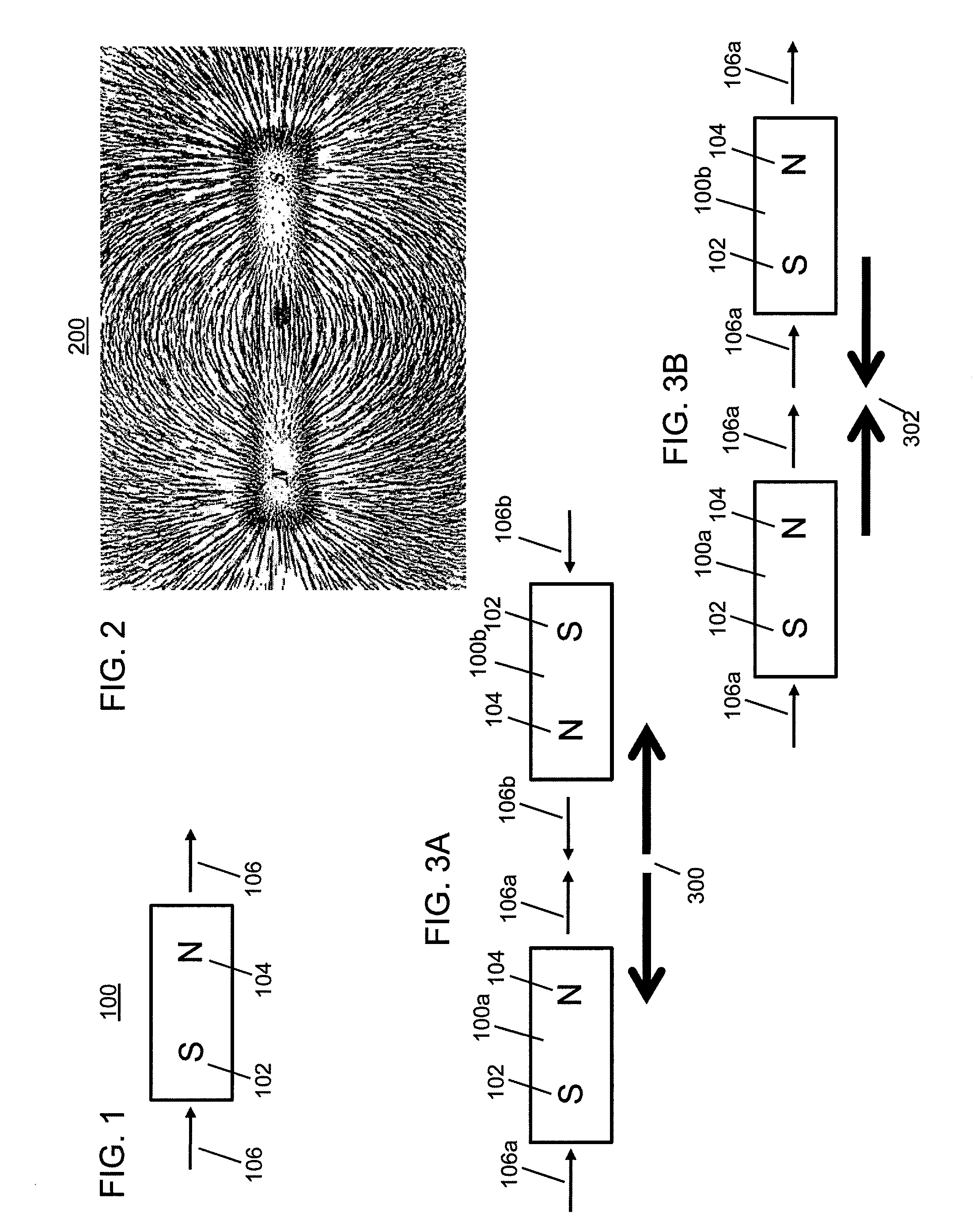
[0113]FIG. 1 depicts South and North poles and magnetic field vectors of an exemplary magnet. Referring to FIG. 1, a magnet 100 has a South pole 102 and a North pole 104. Also depicted are magnetic field vectors 106 that represent the direction and magnitude of the magnet's moment. North and South poles are also referred to herein as positive (+) and negative (−) poles, respectively. In accordance with the invention, magnets can be permanent magnets, impermanent magnets, electromagnets, electro-permanent magnet...


PUM


Abstract

An improved field emission system and method is provided that involves field emission structures having electric or magnetic field sources. The magnitudes, polarities, and positions of the magnetic or electric field sources are configured to have desirable correlation properties, which may be in accordance with a code. The correlation properties correspond to a desired spatial force function where spatial forces between field emission structures correspond to relative alignment, separation distance, and the spatial force function.

Description

CROSS-REFERENCE TO RELATED APPLICATIONS[0001]This Non-provisional application is a continuation-in-part of Non-provisional application Ser. No. 12 / 123,718, filed May 20, 2008, titled “A Field Emission System and Method”, which claims the benefit of U.S. Provisional Application Ser. No. 61 / 123,019, filed Apr. 4, 2008, titled “A Field Emission System and Method”, which is incorporated by reference herein in its entirety.FIELD OF THE INVENTION[0002]The present invention relates generally to a field emission system and method. More particularly, the present invention relates to a system and method where correlated magnetic and / or electric field structures create spatial forces in accordance with the relative alignment of the field emission structures and a spatial force function.BACKGROUND OF THE INVENTION[0003]Alignment characteristics of magnetic fields have been used to achieve precision movement and positioning of objects. A key principle of operation of an alternating-current (AC) ...

Claims


Application Information

Patent Timeline
IPC IPC(8): H01F7/02
CPCH01F7/0284Y10T24/32H01F13/00H01F7/122H01F27/06H01F27/306H01F30/12H01F41/0226
Inventor FULLERTON, LARRY W.ROBERTS, MARK D.RICHARDS, JAMES L.
Owner CORRELATED MAGNETICS RES LLC
Why Eureka
Try Eureka