Liquid crystal display device

Inactive Publication Date: 2009-11-05
JAPAN DISPLAY WEST
View PDF0 Cites 13 Cited by
  • Summary
  • Abstract
  • Description
  • Claims
  • Application Information

AI Technical Summary

Benefits of technology

[0020]According to such a configuration, when a trench is formed in a liquid crystal layer thickness-adjustment layer formed of a transparent resin layer so that a pathway for a surplus material for alignment film is constructed by the trench, the surplus one of the material for alignment film to be applied on the surface of the transparent resin layer can escape from both sides of the transparent resin layer. Therefore, according to the liquid crystal display device of the invention, it is possible to suppress the disorder of liquid crystal molecule alignment due to the step of the liquid crystal layer thickness-adjustment layer (multi-gap layer). Thus, occurrence of thickness unevenness of the alignment film can be suppressed, and so-called alignment defects such as distortion or non-uniformity of the alignment of the liquid crystal molecules can be reduced, whereby a liquid crystal display device having a good display quality can be obtained. In addition, when the bottom position of the trench of the liquid crystal layer thickness-adjustment layer is lower than the height of the color filter layer from the surface of the transparent substrate and the transparent resin layer exists on the bottom of the trench, the depth of the trench can be decreased compared with the known example. Therefore, it is possible to decrease the area of the inclined portion of the step due to the trench formed in the liquid crystal layer thickness-adjustment layer and to thus decrease the area of a disclination occurring region. Therefore, according to the liquid crystal display device of the invention, it is possible to obtain a liquid crystal display device having a high aperture ratio and a good display quality.Application 3 and 4
[0033]According to such a configuration, since the liquid crystal layer thickness-adjustment layer is formed in the reflective region, it is possible to equalize the optical path length of the reflective portion and the transmissive portion so that an image displayed on the reflective portion has the same color tone as the image displayed on the transmissive portion. In addition, since the liquid crystal display device of the invention is able to perform monochromatic display in the reflective display mode, in this case, the image displayed on the reflective portion can be easily perceived.

Problems solved by technology

Moreover, when an electrode, a color filter layer, a multi-gap layer, a common electrode, a light shielding film, and the like are formed on a transparent substrate, and an material for alignment film is then applied by a roller, a surplus material for alignment film may remain close to a boundary of the step between the reflective portion and the transmissive portion due to the multi-gap layer, and thus, thickness unevenness of the alignment film may occur.
Therefore, although this part of the trench 22e is shielded by the light shielding film 25 similar to the gap 21e between the adjacent color filter layers 19, since this part does not contribute to display, there is a problem that the aperture ratio of the liquid crystal display device decreases.
Such a problem is particularly so because the step of the trench 22e may increase in the case of a display panel configured to perform color display in a transmissive display mode and monochromatic display in a reflective display mode and having no color filter layer on the reflective portion.
As a result, the display quality may deteriorate greatly compared with the case of a display panel configured to perform color display in both transmissive display mode and reflective display mode.
According to such a configuration, when the inclination angle of the sidewalls of the trench formed in the liquid crystal layer thickness-adjustment layer with respect to the transparent substrate is equal to or smaller than 60 degree, the area of the alignment disorder region increases, and thus, it is not desirable.

Method used


Image

  • Liquid crystal display device
  • Liquid crystal display device
  • Liquid crystal display device

Examples


first embodiment

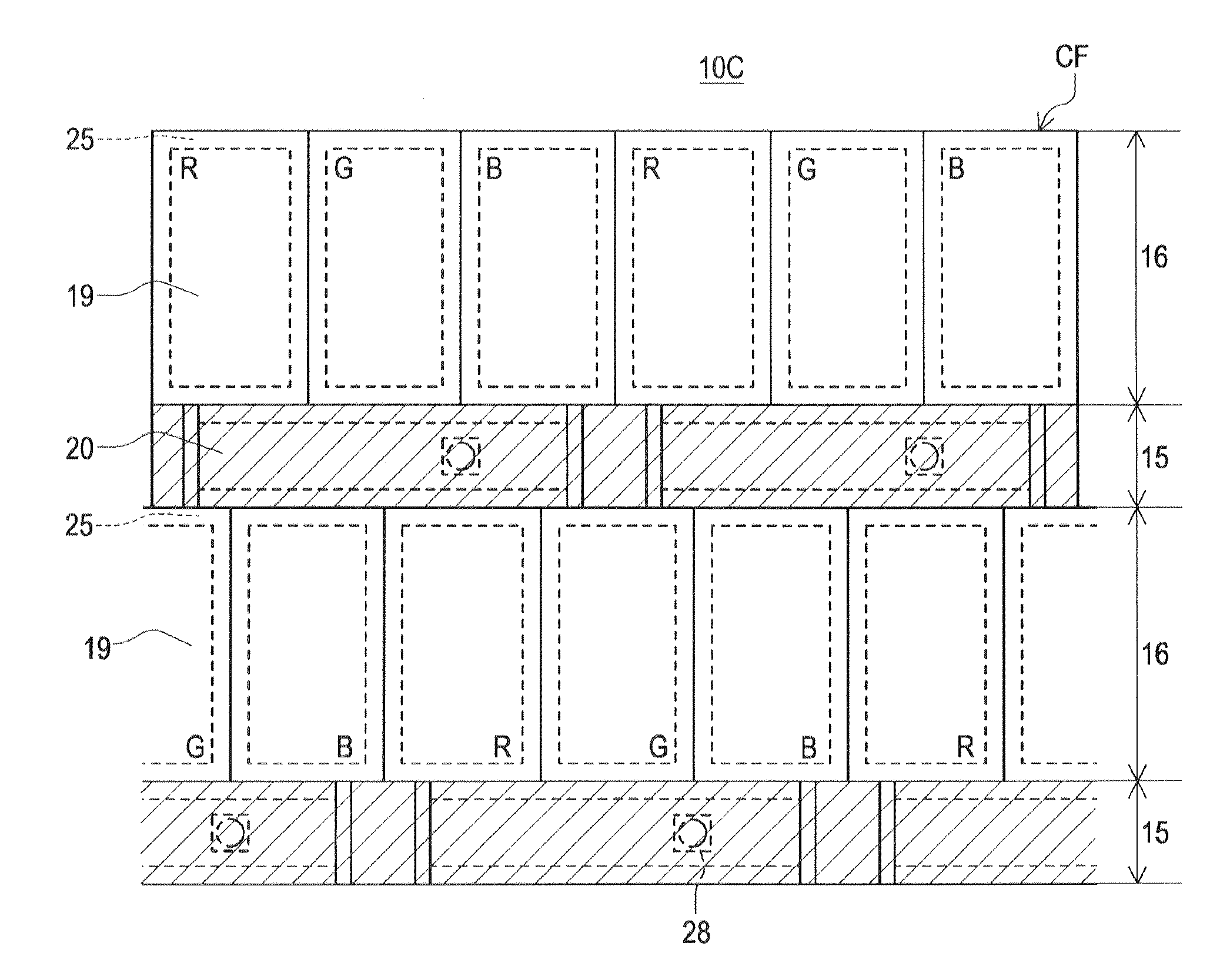
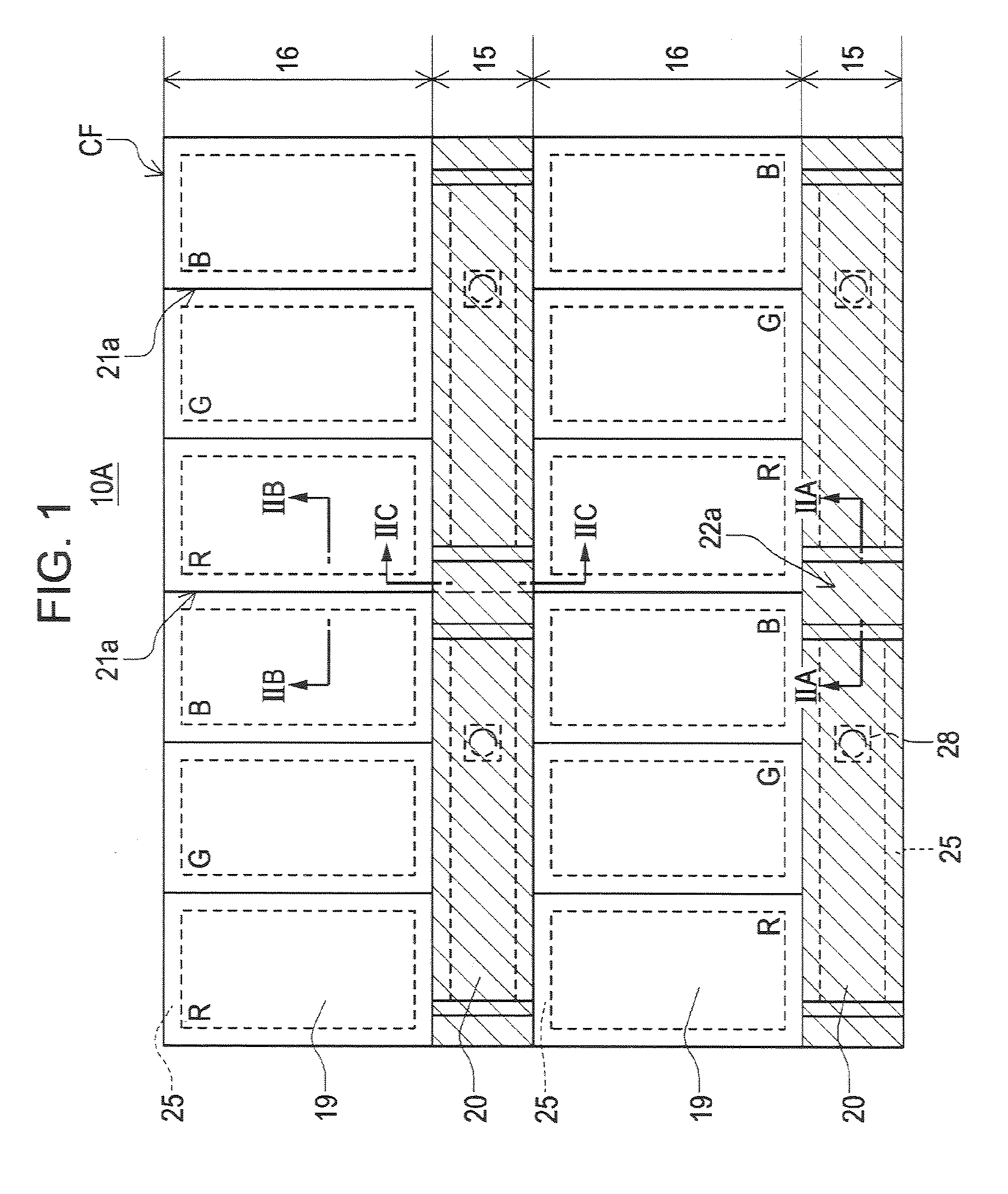
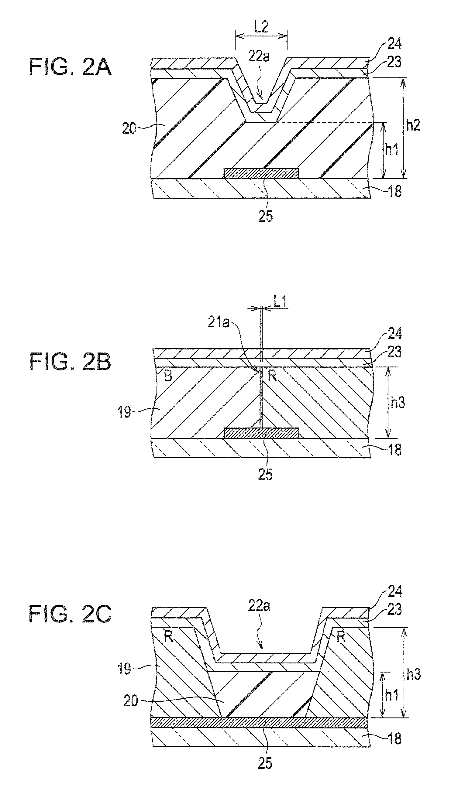
[0047]FIG. 1 is a schematic plan view of a color filter substrate of a transflective type liquid crystal display device according to a first embodiment, corresponding to four pixels. FIG. 2A is a cross-sectional view taken along the line IIA-IIA in FIG. 1, FIG. 2B is a cross-sectional view taken along the line IIB-IIB in FIG. 1, and FIG. 2C is a cross-sectional view taken along the line IIC-IIC in FIG.

[0048]As illustrated in FIG. 1, in a color filter substrate CF of a transflective type liquid crystal display device 10A according to this embodiment, a reflective portion 15 for performing monochromatic display and a transmissive portion 16 having therein respective color filter layers 19 corresponding to colors R, G and B arranged in a stripe form are arranged in a matrix form. In the transflective type liquid crystal display device 10A having the color filter layers 19 corresponding to three colors of R, G and B, one pixel is formed by three sub-pixels corresponding to the colors of...

modification 1

[0052]Although the transflective type liquid crystal display device 10A according to the above embodiment has been described with respect to an example where the bottom of the trench 22a formed in the multi-gap layer 20 is partly flat in a row direction, the trench may have a V shape in cross-sectional view as long as the transparent resin layer exists on the bottom of the trench and the condition of h2>h3>h0>0 is satisfied. FIG. 3 is a schematic plan view of a color filter substrate of a transflective type liquid crystal display device according to this modification, corresponding to four pixels. FIG. 4A is a cross-sectional view taken along the line IVA-IVA in FIG. 3, FIG. 4B is a cross-sectional view taken along the line IVB-IVB in FIG. 3, and FIG. 4C is a cross-sectional view taken along the line IVC-IVC in FIG. 3. Since a transflective type liquid crystal display device 10B according to this modification has the same configuration as that of the transflective type liquid crysta...

modification 2

[0053]The trenches 22a and 22b formed in the multi-gap layer 20 have inclined portions (sidewalls) thereof having an inclination angle of preferably 60 to 85 degree with respect to the transparent substrate 18. When the inclination angle of the inclined portions of the trenches 22a and 22b formed in the multi-gap layer 20 with respect to the transparent substrate 18 is equal to or smaller than 60 degree, the area of an alignment disorder region increases, and thus, it is not desirable. When the inclination angle is greater than 85 degree, the material for alignment film becomes hard to flow therein.

[0054]FIG. 5 is a cross-sectional view of the portion corresponding to FIG. 4A, for explaining the relationship between an inclination angle and a light shielding width of an inclined surface of a trench. For example, as illustrated in FIG. 5, when a width of a portion of the light shielding film 25 to be shielded, corresponding to an inclined portion of the trench having a larger inclina...


PUM


Abstract

A liquid crystal display device is provided which includes a substrate having a pixel electrode; and a color filter substrate having a color filter layer on a transparent substrate while having an alignment film formed on an uppermost layer thereof, the substrate and the color filter substrate each having a display region having a plurality of sub-pixels formed thereon, in which the color filter substrate has a liquid crystal layer thickness-adjustment layer formed of a transparent resin layer being partially formed on an inner side of the alignment film; and the liquid crystal layer thickness-adjustment layer has a trench being formed along and between adjacent ones of the sub-pixels, the bottom position of the trench of the liquid crystal layer thickness-adjustment layer being lower than a height of the color filter layer from a surface of the transparent substrate, and the transparent resin layer existing on the bottom of the trench.

Description

[0001]This application claims the benefit of Japanese Patent Application No. 2008-118146, filed on Apr. 30, 2008, and Japanese Patent Application No. 2008-210318, filed on Aug. 19, 2008. The entire disclosures of the prior applications are hereby incorporated by reference herein in their entirety.BACKGROUND[0002]1. Technical Field[0003]The present invention relates to a liquid crystal display device, and more particularly, to a liquid crystal display device capable of achieving a good display quality, a high aperture ratio and a high display luminance even when a multi-gap layer (liquid crystal layer thickness-adjustment layer) formed of a transparent resin layer is provided on a color filter substrate.[0004]2. Related Art[0005]In recent years, as a liquid crystal display device used for portable apparatuses typified by cellular phones, a transflective type liquid crystal display devices employing both transmissive and reflective display modes has been widely used. The transflective...

Claims


Application Information

Patent Timeline
IPC IPC(8): G02F1/1335
CPCG02F1/133555
Inventor UEHARA, TOSHINORIYOSHIDA, KOJIYOSHIDA, SHUHEI
Owner JAPAN DISPLAY WEST
Why Eureka
Try Eureka