Gas bearing electrostatic chuck

Active Publication Date: 2009-11-05
AXCELIS TECHNOLOGIES
View PDF36 Cites 25 Cited by
  • Summary
  • Abstract
  • Description
  • Claims
  • Application Information

AI Technical Summary

Benefits of technology

[0012]A first voltage potential is further applied to the first electrode, therein generally attracting the workpiece to the clamping plate with a first attractive force. The first gas pressure and first voltage potential, for example, are further controlled, wherein the first repelling force and first attractive force are generally equalized. Thus, the workpiece generally “floats” on a cushion of gas, thus generally eliminating contact between the workpiece and the electrostatic clamp.

Problems solved by technology

However, increasing the clamping force on the entire workpiece can have deleterious effects, such as increased particulate contamination, since the increased clamping pressure can cause frictional forces between the ESC and the workpiece across the surface of the workpiece, thus leading to greater chances of particulate contamination across the areas of the workpiece in which devices are formed.

Method used


Image

  • Gas bearing electrostatic chuck
  • Gas bearing electrostatic chuck
  • Gas bearing electrostatic chuck

Examples


Embodiment Construction

[0021]The present invention is directed generally toward an electrostatic clamp or chuck (ESC) that provides improved clamping and thermal uniformity, while further decreasing backside particle contamination. Accordingly, the present invention will now be described with reference to the drawings, wherein like reference numerals may be used to refer to like elements throughout. It should be understood that the description of these aspects are merely illustrative and that they should not be interpreted in a limiting sense. In the following description, for purposes of explanation, numerous specific details are set forth in order to provide a thorough understanding of the present invention. It will be evident to one skilled in the art, however, that the present invention may be practiced without these specific details.

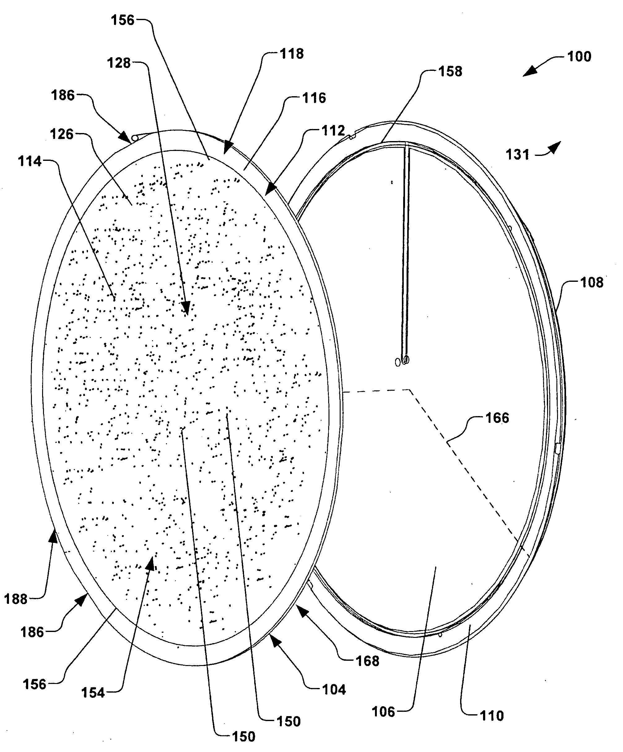
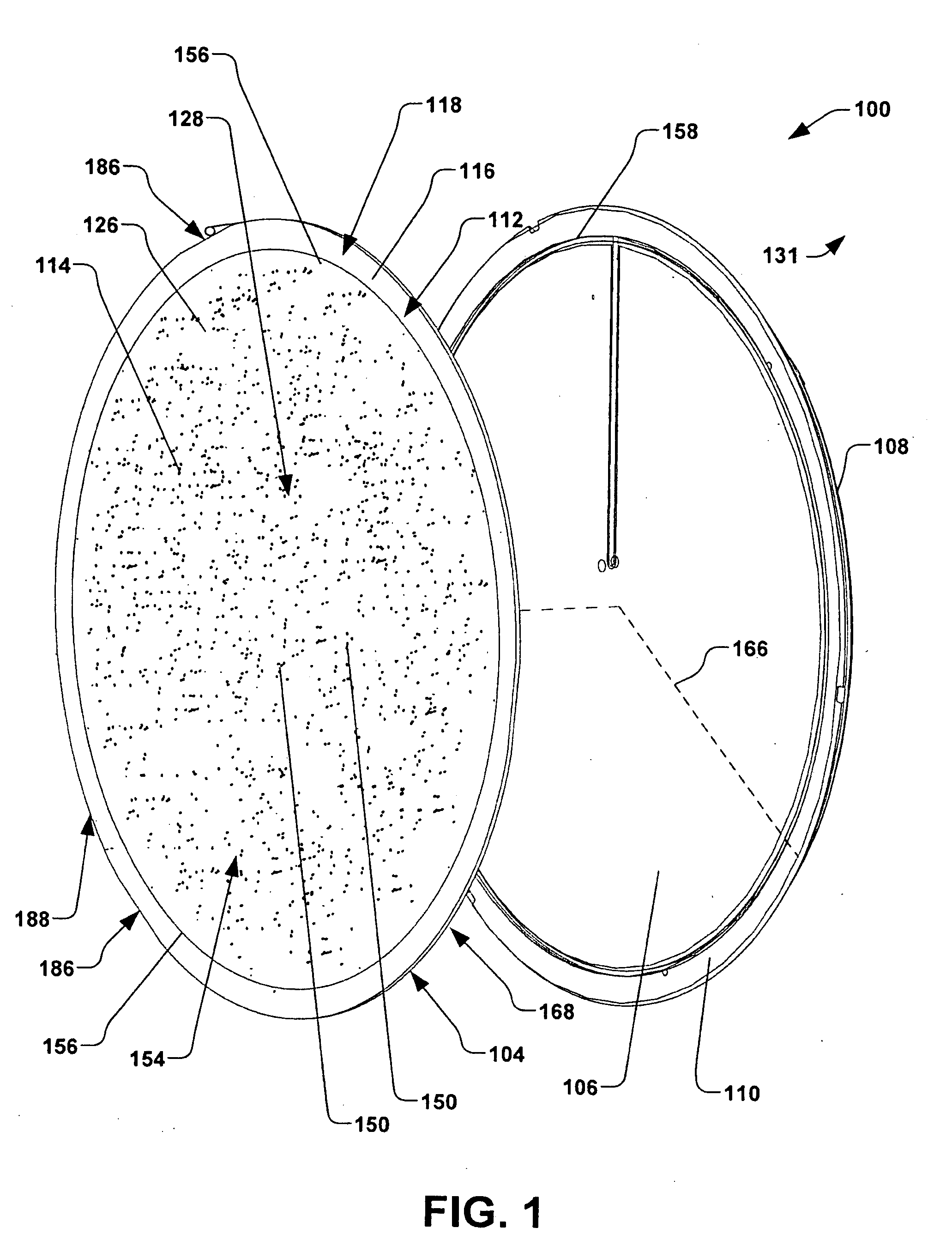
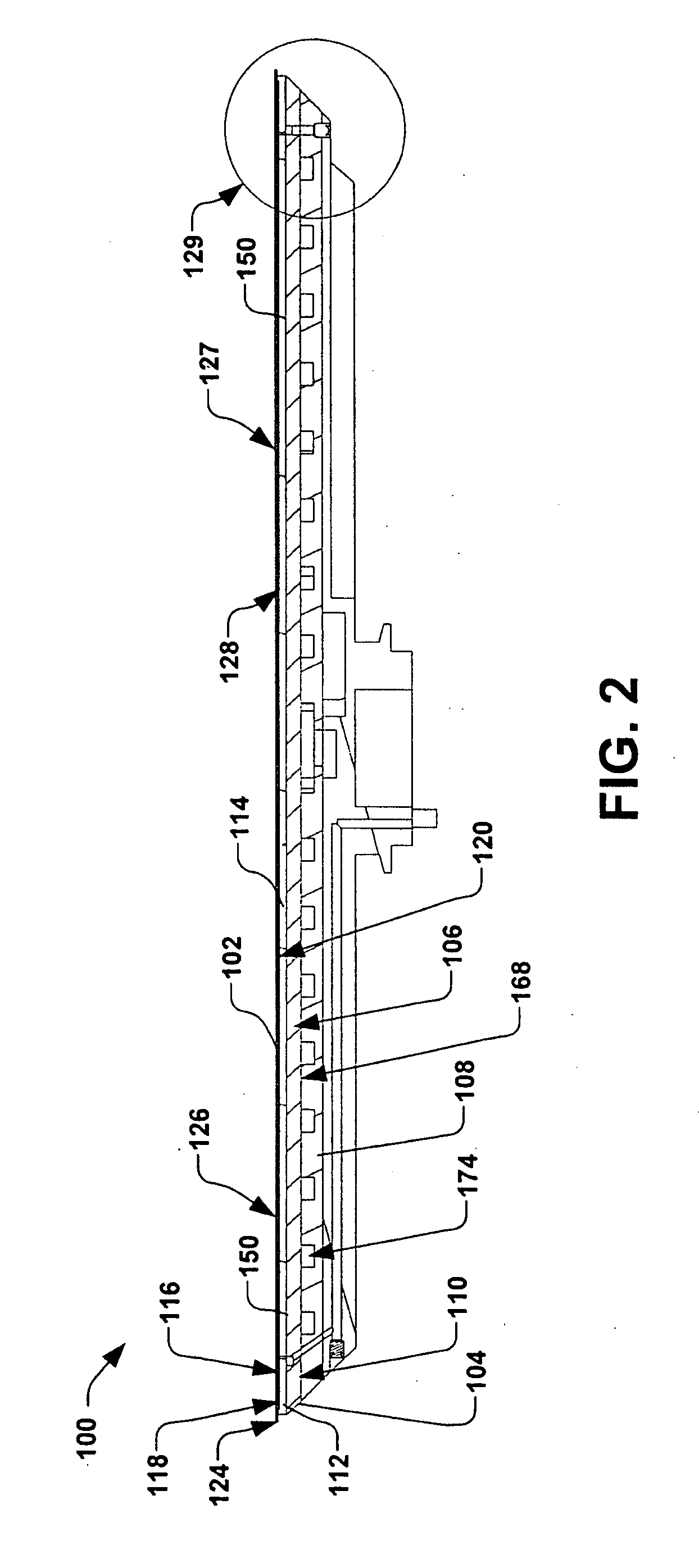
[0022]Referring now to the figures, FIG. 1 illustrates an exploded perspective view of an exemplary electrostatic clamp 100, also referred to as an “ESC”. The ESC 100 is ...


PUM


Abstract

An electrostatic clamp is provided having a clamping plate, wherein the clamping plate has a central region and an annulus region. A plurality of gas supply orifices are defined in the central region of the clamping plate, wherein the plurality of gas supply orifices are in fluid communication with a pressurized gas supply, and wherein the pressurized gas supply is configured to provide a cushion of gas between the clamping surface and the workpiece in the central region of the clamping plate via the plurality of gas supply orifices. One or more gas return orifices defined in one or more of the central region and annulus region of the clamping plate, wherein the one or more gas return orifices are in fluid communication with a vacuum source, therein generally defining an exhaust path for the cushion of gas. A seal is disposed in the annulus region of the clamping plate, wherein the seal is configured to generally prevent a leakage of the cushion of gas from the central region to an environment external to the annulus region. One or more electrodes are further electrically connected to a first voltage potential to provide a first clamping force.

Description

FIELD OF THE INVENTION[0001]The present invention relates generally to semiconductor processing clamping systems, and more specifically to an electrostatic clamp and method of clamping workpieces.BACKGROUND OF THE INVENTION[0002]Electrostatic clamps or chucks (ESCs) are often utilized in the semiconductor industry for clamping workpieces or substrates during plasma-based or vacuum-based semiconductor processes such as ion implantation, etching, chemical vapor deposition (CVD), etc. Clamping capabilities of the ESCs, as well as workpiece temperature control, have proven to be quite valuable in processing semiconductor substrates or wafers, such as silicon wafers. A typical ESC, for example, comprises a dielectric layer positioned over a conductive electrode, wherein the semiconductor wafer is placed on a surface of the ESC (e.g., the wafer is placed on a surface of the dielectric layer). During semiconductor processing (e.g., ion implantation), a clamping voltage is typically applied...

Claims


Application Information

Patent Timeline
IPC IPC(8): H02N13/00
CPCH01L21/6831
Inventor LEE, WILLIAM DAVIDLAFONTAINE, MARVIN RAYMONDPUROHIT, ASHWIN MADHUKARGILLESPIE, JOSEPH DANIELBECKEL, DONOVANTAO, TENG CHAOSLOCUM, ALEXANDER HENRYNAYFEH, SAMIR
Owner AXCELIS TECHNOLOGIES
Why Eureka
Try Eureka