Nanofiber production device and nanofiber production method

Inactive Publication Date: 2011-11-17
PANASONIC CORP
View PDF3 Cites 8 Cited by
  • Summary
  • Abstract
  • Description
  • Claims
  • Application Information

AI Technical Summary

Benefits of technology

[0021]According to the present invention, it is possible to eliminate contact between the supplying electrode, which supplies electric charge to the effusing body, and the effusing body, and the electric charge is supplied to the effusing body without generating friction.

Problems solved by technology

However, for example, when many nozzles are arranged as the device described in Patent Literature (PTL) 1, a problem occurs.
For example, potential of the nozzles to which a high voltage is applied does not stabilize, and nanofibers are produced only from a part of the solution effused into the space.

Method used


Image

  • Nanofiber production device and nanofiber production method
  • Nanofiber production device and nanofiber production method
  • Nanofiber production device and nanofiber production method

Examples


Embodiment Construction

[0031]Following describes an embodiment of a nanofiber production device according to the present invention with reference to the drawings.

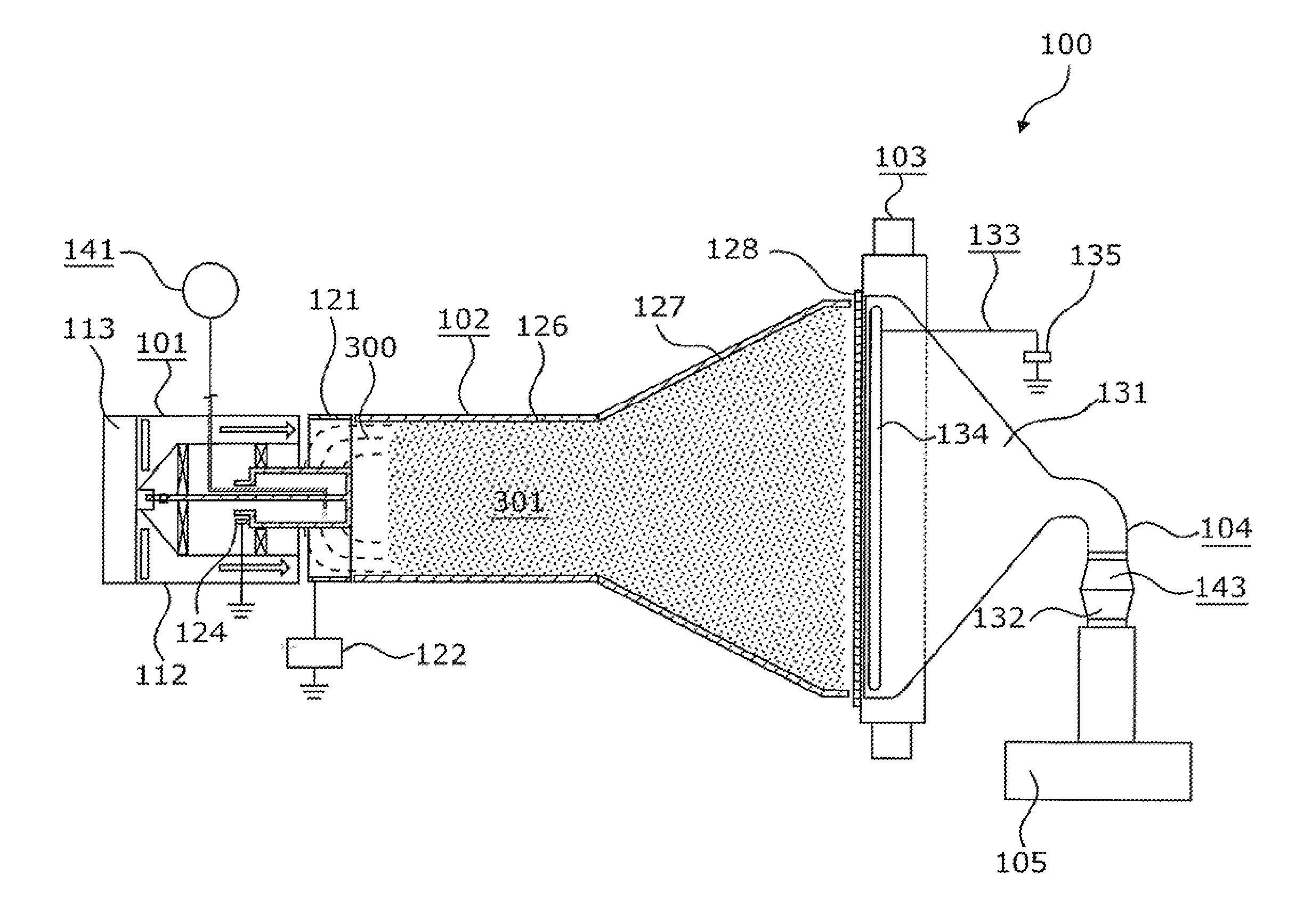
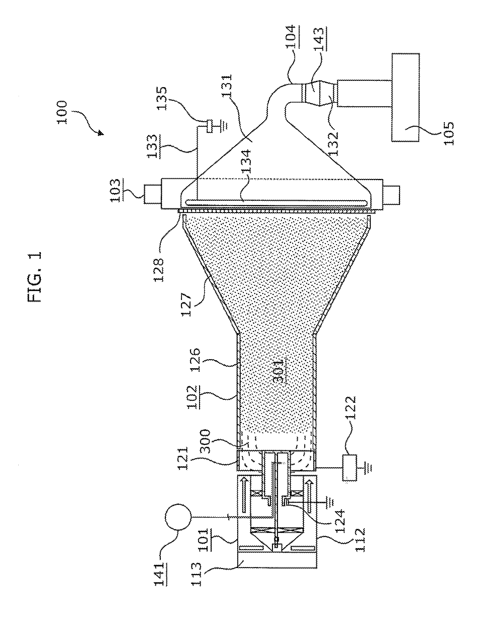
[0032]FIG. 1 is a partially cutaway plan view of an embodiment of the nanofiber production device.

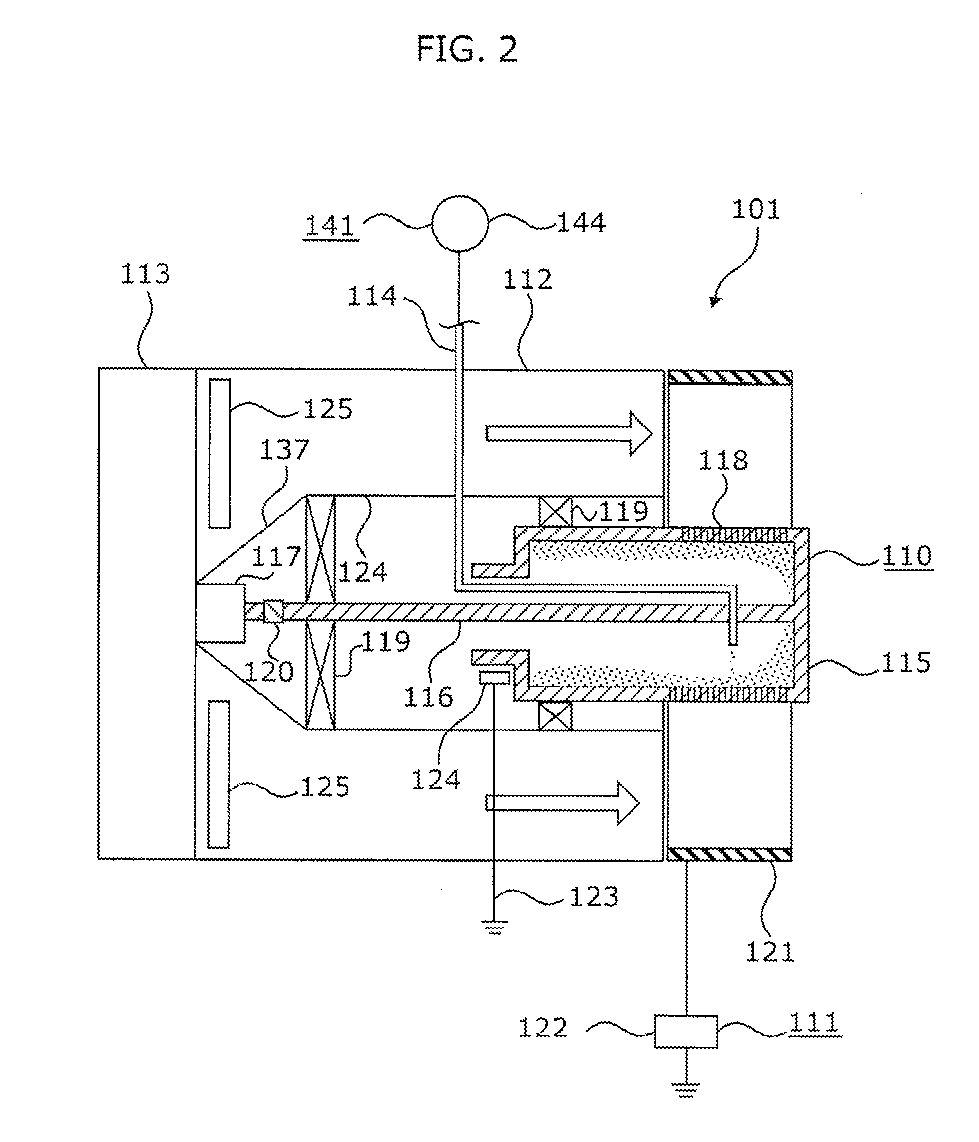
[0033]As shown in FIG. 1, a nanofiber production device 100 includes: a discharging device 101, a guiding body 102, a collecting device 103, an attracting device 104, and a gas flow generating device 113.

[0034]Note that a raw material liquid used for producing the nanofibers is referred to as the solution 300, and the produced nanofibers are referred to as the nanofibers 301. However, the solution 300 changes to the nanofibers 301 while electrically stretched in the production of the nanofibers; and thus, the border between the solution 300 and the nanofibers 301 is ambiguous and they cannot be clearly distinguished from each other.

[0035]The discharging device 101 is a unit which can discharge, by gas flow, the solution 300 which is charged and nanof...


PUM

PropertyMeasurementUnit
Electric potential / voltageaaaaaaaaaa
Distanceaaaaaaaaaa

Abstract

A nanofiber production device (100) produces nanofibers (301) by stretching, in space, a solution (300). The nanofiber production device (100) includes: an effusing body (115) which effuses the solution (300) into the space by centrifugal force; a driving source (117) which rotates the effusing body (115); a supplying electrode (124) which is placed at a predetermined distance from the effusing body (115) and supplies charge to the solution (300) via the effusing body (115); a charging electrode (121) to which a potential of reverse polarity to a polarity of the effusing body (115) is applied, the charging electrode (121) is placed at a predetermined distance from the effusing body (115); and a charging power source (122) which applies a predetermined voltage between the supplying electrode (124) and the charging electrode (121).

Description

TECHNICAL FIELD[0001]The present invention relates to nanofiber production devices and nanofiber production methods, and in particular to a nanofiber production device and a nanofiber production method that allow increased device durability and nanofiber production efficiency.BACKGROUND ART[0002]Electrospinning (electric charge induced spinning) is known as a method for producing filamentous (fibrous form) substances (nanofibers) made of polymeric substances or the like and having a diameter in a submicron scale.[0003]In the electrospinning method, a solution, which is a raw material liquid prepared by dispersing or dissolving polymeric substances or the like in a solvent, is effused (ejected) into a space through a nozzle or the like, while charging the solution by applying an electric charge. The solution traveling the space is electrically stretched, and nanofibers are thus produced.[0004]Following describes the electrospinning method more specifically. The solution which is elec...

Claims


Application Information

Patent Timeline
IPC IPC(8): B29B9/06B82Y40/00D04H1/42D04H1/4291D04H1/728
CPCD01D5/0061D01D5/0069D04H1/728D04H1/42D04H1/4291D01D5/18D04H1/43838
Inventor ISHIKAWA, KAZUNORIKUROKAWA, TAKAHIROSUMIDA, HIROTOYOKOYAMA, MASAHIDE
Owner PANASONIC CORP
Why Eureka
Try Eureka