Dynamic Switch Contact Protection

Active Publication Date: 2009-11-05
KEYSIGHT TECH
View PDF12 Cites 10 Cited by
  • Summary
  • Abstract
  • Description
  • Claims
  • Application Information

AI Technical Summary

Problems solved by technology

Often the switches that switch the fastest at the lowest currents and voltages have physical contacts that are susceptible to damage.
Damage, or abuse, can be the result of electrical transient effects that occur during the make or break cycle of the switch.
Replacing thousands of relays at regular intervals or replacing selected worn out relays is an undesirable expense.
While these switch contacts can be protected by the use of current-limiting resistors in the path of the switch, the resistors sometimes add undesired impedance to a circuit.
As the switch closes, very high currents can flow from circuit capacitances damaging the switch.
Damage on switch closure is due primarily to an excessive surge in current, also called in-rush current.
Small micro-welds develop on the surface of the switch contacts over time and the contacts become irregular and pitted.
Catastrophic failure during closure for most switches is a stuck close condition.
Damage on opening the switch is due primarily to an excessive surge in voltage causing arcing.
This arc also damages the switch contacts.
This arc ca

Method used


Image

  • Dynamic Switch Contact Protection
  • Dynamic Switch Contact Protection
  • Dynamic Switch Contact Protection

Examples


Embodiment Construction

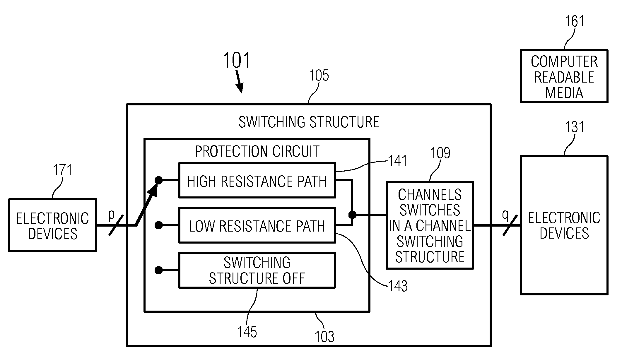
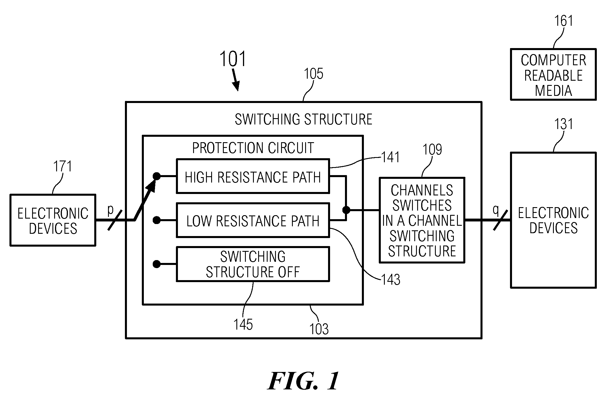
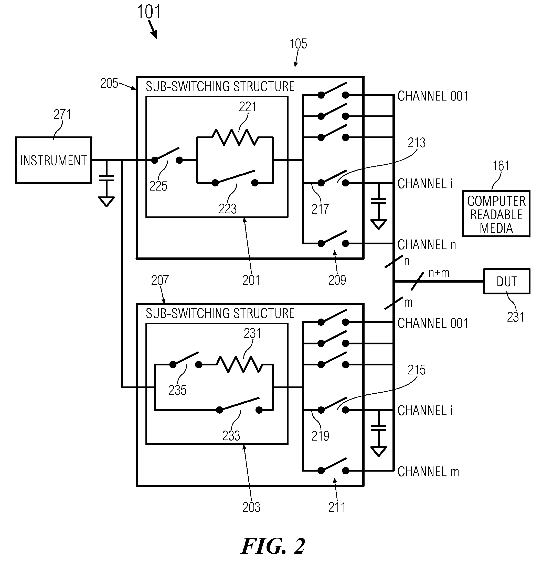
[0015]A dynamic switch contact protection (“dynamic protection”) circuit and technique is described herewith as a solution to the problems described above. The dynamic protection comprises switching to a high resistance path to reduce the electrical transient effects when opening and closing a channel switch. The dynamic protection also comprises switching to a low resistance path for connecting the electronic devices through the channel switch for making measurements with the electronic devices. The dynamic protection further comprises disconnecting a channel switching structure to isolate the channel switching structure from the electrical system.

[0016]The dynamic protection technique uses a current-limiting resistor in series with the channel switch. The added resistance of the current-limiting resistor lessens the abuse (described above), thereby protecting the channel switches of the measurement path, and increasing their usable lifetimes. When sequenced, the technique provides...


PUM


Abstract

A dynamic switch contact protection circuit and technique to protect a channel switch within an electrical system by limiting transients when the switch is turned on or turned off. The protection circuit comprises switching between a high resistance path and a low resistance path. The high resistance path comprises a resistor. A bypass switch is connected in parallel to the resistor to affect the low resistance path. The protection circuit can connect or disconnect switch cards to the electrical system enabling the creation of a larger switching structure. Disconnected switch cards within a switching structure preserves system bandwidth by limiting capacitive loading. Electing which switch to close last or open first can prolong the length of usage of the switches.

Description

BACKGROUND OF THE INVENTION[0001]Various types of switches are used in electronic test and measurement systems to switch or route signals between a stimulus, measuring instruments, and devices-under-test (DUTs). Often the switches that switch the fastest at the lowest currents and voltages have physical contacts that are susceptible to damage. Damage, or abuse, can be the result of electrical transient effects that occur during the make or break cycle of the switch. Measurement can be defined as the process of testing or exercising a circuit using both sources and detectors.[0002]Switches common in the art are reed relays, armature relays, and electronic or solid-state switches.[0003]Reed relays are used in switching platforms that employ thousands of such switches. Replacing thousands of relays at regular intervals or replacing selected worn out relays is an undesirable expense.[0004]While these switch contacts can be protected by the use of current-limiting resistors in the path o...

Claims


Application Information

Patent Timeline
IPC IPC(8): G01R31/08
CPCG01R31/28H02H9/001
Inventor BOSWELL, BRYAN D.LEIBY, ROBERT W.NARCISO, STEVEN J.
Owner KEYSIGHT TECH
Why Eureka
Try Eureka