Wear Assembly For Excavating Equipment

a technology of excavating equipment and wear, which is applied in the direction of soil shifting machines/dredgers, machines/dredgers working methods, construction, etc., can solve the problems of inability of operators to see the ground, inability to effectively guide the cutterhead along a path best suited to the terrain, and considerable power is needed to drive the cutterhead. , to achieve the effect of reducing power consumption, minimizing drag, and minimizing the power needed to drive the equipmen

Inactive Publication Date: 2009-11-12
ESCO CORP
View PDF80 Cites 16 Cited by
  • Summary
  • Abstract
  • Description
  • Claims
  • Application Information

AI Technical Summary

Benefits of technology

[0005]In accordance with one aspect of the invention, a wear member for excavating equipment is formed with side relief in the working and mounting sections to minimize the drag associated with the digging operation and, in turn, minimize the power needed to drive the equipment. Reduced power consumption, in turn, leads to a more efficient operation and a longer usable life for the wear member.

Problems solved by technology

Further difficulties are caused by the operator's inability to see the ground that is being excavated underneath the water; i.e., unlike most other excavating operations, the dredge cutterhead cannot be effectively guided along a path to best suit the terrain to be excavated.
Consequently, considerable power is needed to drive the cutterhead, particularly when excavating in rock.
However, as the bit becomes shorter due to wear, the mounting sections of the points will begin to engage the ground in the cutting operation.

Method used


Image

  • Wear Assembly For Excavating Equipment
  • Wear Assembly For Excavating Equipment
  • Wear Assembly For Excavating Equipment

Examples


Embodiment Construction

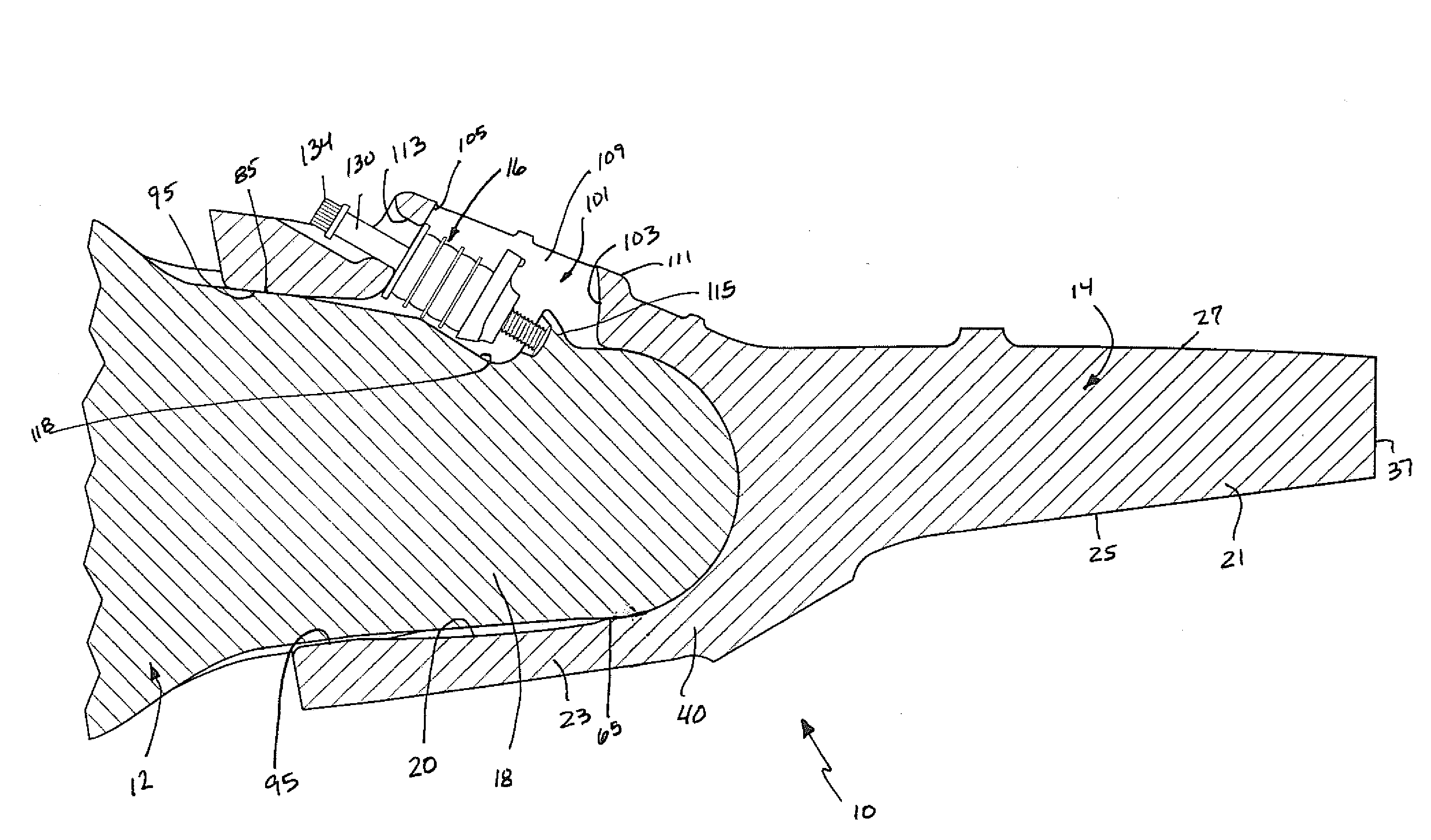
[0045]The present invention pertains to a wear assembly 10 for excavating equipment, and is particularly well suited for dredging operations. In this application, the invention is described in terms of a dredge tooth adapted for attachment to a dredge cutterhead. Nevertheless, the different aspects of the invention can be used in conjunction with other kinds of wear assemblies (e.g., shrouds) and for other kinds of excavating equipment (e.g., buckets).

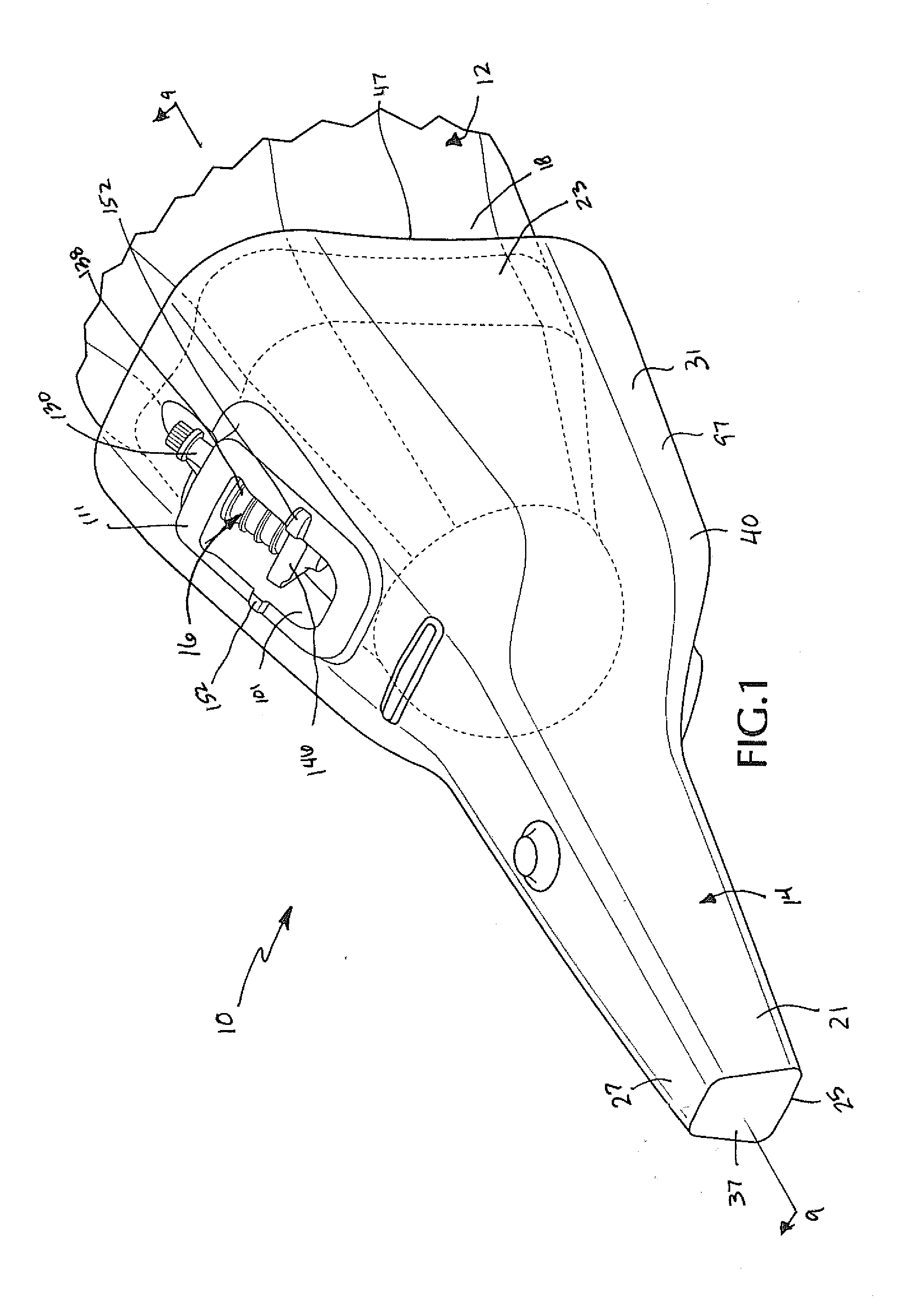
[0046]The assembly is at times described in relative terms such as up, down, horizontal, vertical, front and rear; such terms are not considered essential and are provided simply to ease the description. The orientation of a wear member in an excavating operation, and particularly in a dredge operation, can change considerably. These relative terms should be understood with reference to the orientation of wear assembly 10 as illustrated in FIG. 1 unless otherwise stated.

[0047]Wear assembly 10 includes a base 12 secured to a dredge cutt...


PUM


Abstract

A wear assembly for excavating equipment includes a base fixed to the excavating equipment, a wear member fit over the base, and a lock to releasably hold the wear member to the base. The wear member includes side relief to reduce drag on the system. The wear member and the base each includes a hemispherical front end and a generally trapezoidal rear portion. The base includes a nose and a stop projecting from the nose to cooperate with the lock without an opening being needed to receive the lock into the nose. The lock is an elongate lock positioned generally in an axial direction and which holds the wear member to the base under compressive loads.

Description

FIELD OF THE INVENTION[0001]The present invention pertains to a wear assembly for securing a wear member to excavating equipment, and in particular to a wear assembly that is well suited for attachment and use on a dredge cutterhead.BACKGROUND OF THE INVENTION[0002]Dredge cutterheads are used for excavating earthen material that is underwater, such as a riverbed. In general, a dredge cutterhead 1 includes several arms 2 that extend forward from a base ring 3 to a hub 4 (FIG. 21). The arms are spaced about the base ring and formed with a broad spiral about the central axis of the cutterhead. Each arm 2 is provided with a series of spaced apart teeth 5 to dig into the ground. The teeth are composed of adapters or bases 6 that are fixed to the arms, and points 7 that are releasably attached to the bases by locks 8.[0003]In use, the cutterhead is rotated about its central axis to excavate the earthen material. A suction pipe is provided near the ring to remove the dredged material. To e...

Claims


Application Information

Patent Timeline
Patent Type & Authority Applications(United States)
IPC IPC(8): E02F9/28
CPCE02F9/2825E02F9/2866E02F9/2858E02F9/2841
Inventor OLLINGER, IV, CHARLES G.SNYDER, CHRIS D.KREITZBERG, JOHN S.
Owner ESCO CORP
Why Eureka
Try Eureka