Ultrasonic motor

a technology of ultrasonic motors and motors, applied in piezoelectric/electrostrictive/magnetostrictive devices, piezoelectric/electrostriction/magnetostriction machines, electrical equipment, etc., can solve the problems of reducing the life of the motor, reducing the drive efficiency, and the actual fabrication of the ultrasonic motor always involves a machining error, so as to reduce the cost of manufacturing and manufacturing, less machining processes, and good drive efficiency

Inactive Publication Date: 2009-11-12
SHARP KK
View PDF6 Cites 15 Cited by
  • Summary
  • Abstract
  • Description
  • Claims
  • Application Information

AI Technical Summary

Benefits of technology

[0034]With the configuration described above, an ultrasonic motor that requires less machining processes for the ultrasonic vibrators and has less concern for performance degradation can be obtained.
[0035]According to the ultrasonic motor in accordance with the present invention, an ultrasonic motor with a good drive efficiency and a long life capable of improving the disadvantages of conventional internal contact type ultrasonic motors and driving at four or more contact points can be provided.

Problems solved by technology

Due to the operation principle of the ultrasonic motor, however, if an excessive preload is applied, an ultrasonic vibrator is brought into contact with the driven body in the entire circumference of an elliptical motion, resulting in a reduction in drive efficiency.
Further, a large preload increases wear in a contact point region and reduces the life of the motor.
However, actual fabrication of an ultrasonic motor always involves a machining error.
It is difficult to establish contact at four points in the configuration of FIG. 16, resulting in contact at three points, that is, both ends of one ultrasonic vibrator and one end of the other ultrasonic vibrator.
Thereby, there occurs a problem that desired performance cannot be exhibited.
Actually, however, as shown in FIG. 19, a machining error in the shape of the ultrasonic vibrators is unavoidable, and the shape of the ultrasonic vibrators is not exactly rectangular in most cases.
Further, a deviation in the shape of the ultrasonic vibrators may also occur due to subsequent events such as wear of a contact point.
Therefore, if there occurs a large positional deviation due to the machining error described above, the latter point cannot come into contact with rotor 1 even though it performs the elliptical motion, and thus a desired frictional force may not be able to be obtained.
Such an accuracy is in a range that is extremely difficult to achieve with an ordinary processing method such as machining.
Therefore, there is concern that the torque and the wear might be further worsened than the desired values described above.

Method used


Image

  • Ultrasonic motor
  • Ultrasonic motor
  • Ultrasonic motor

Examples


first embodiment

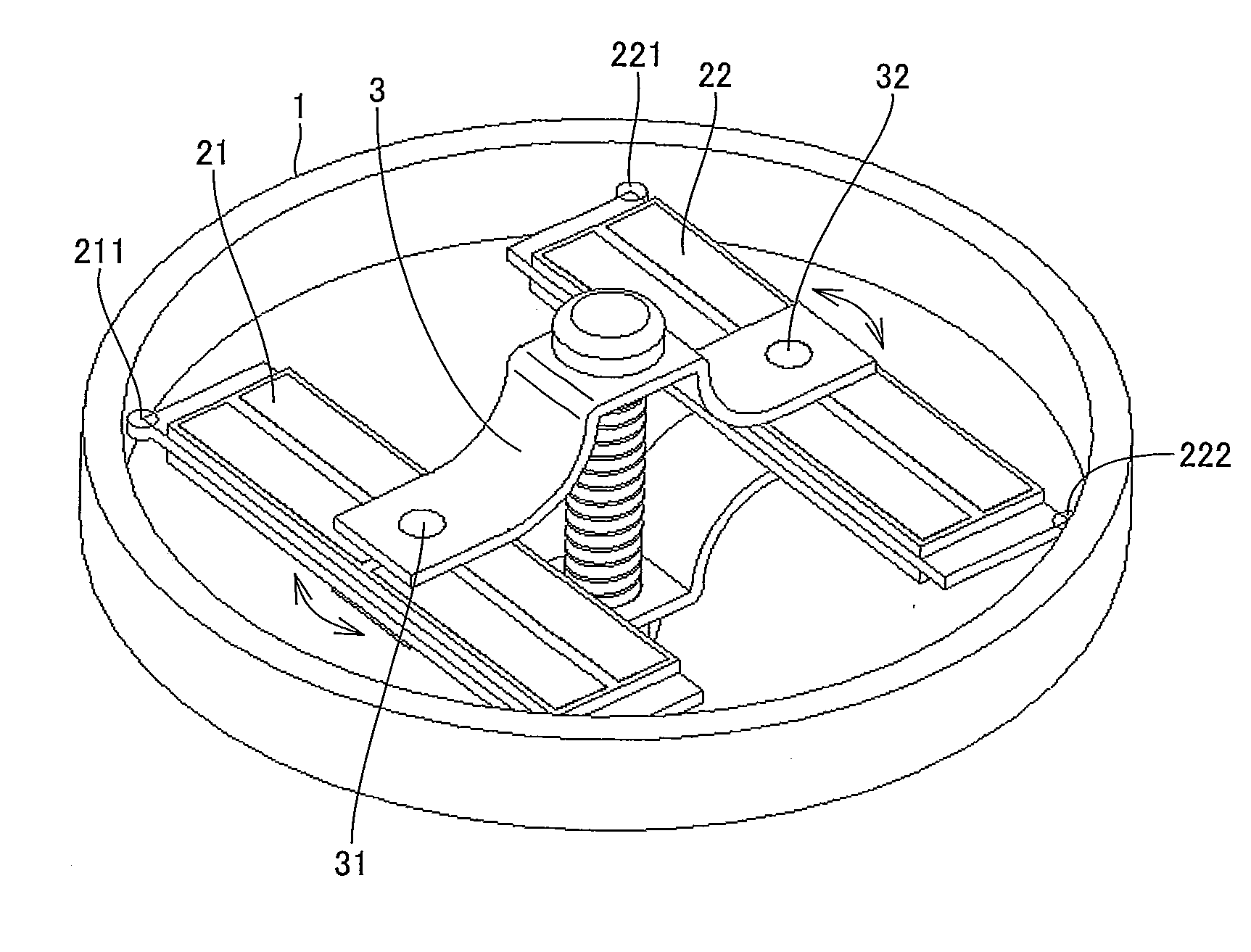
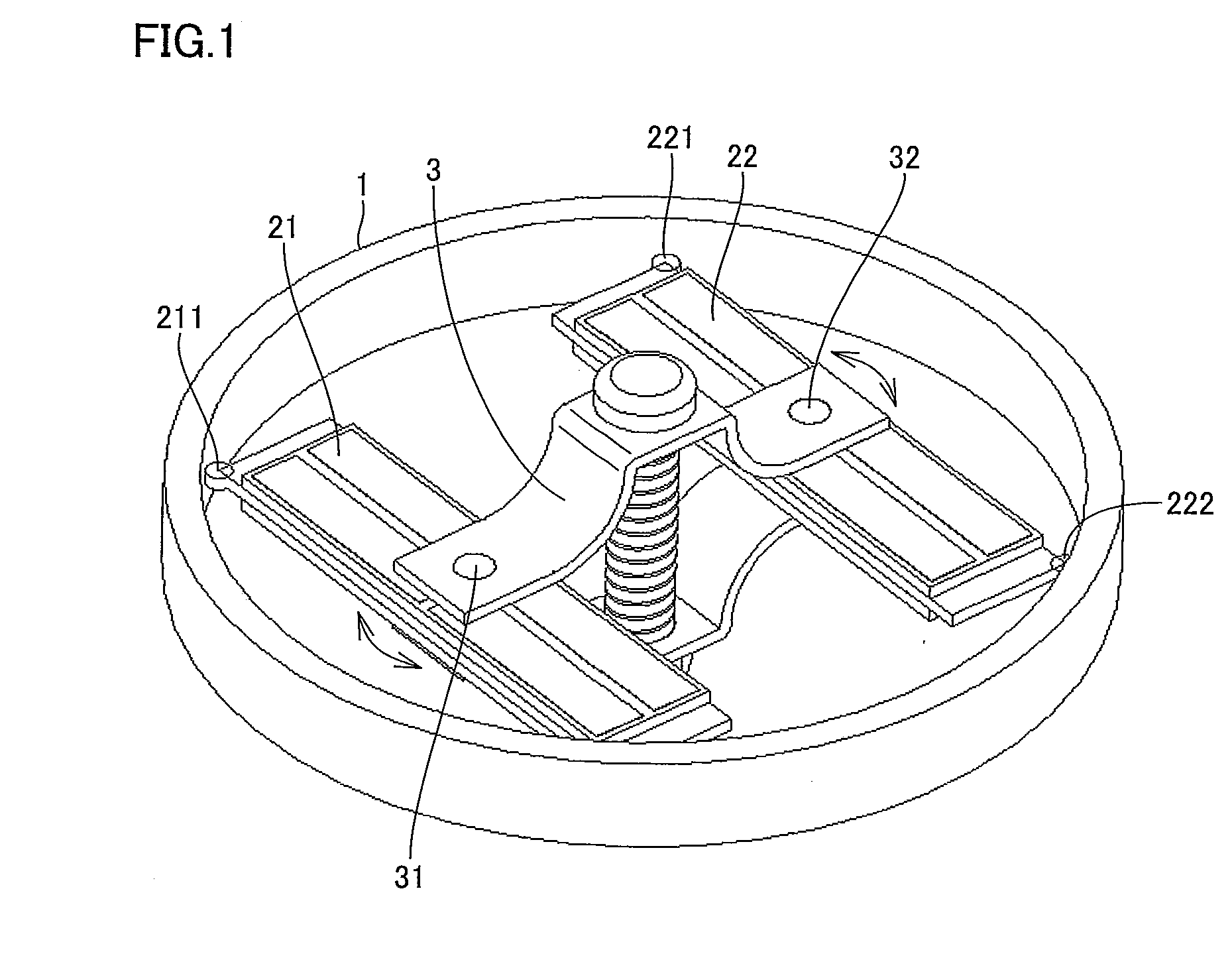
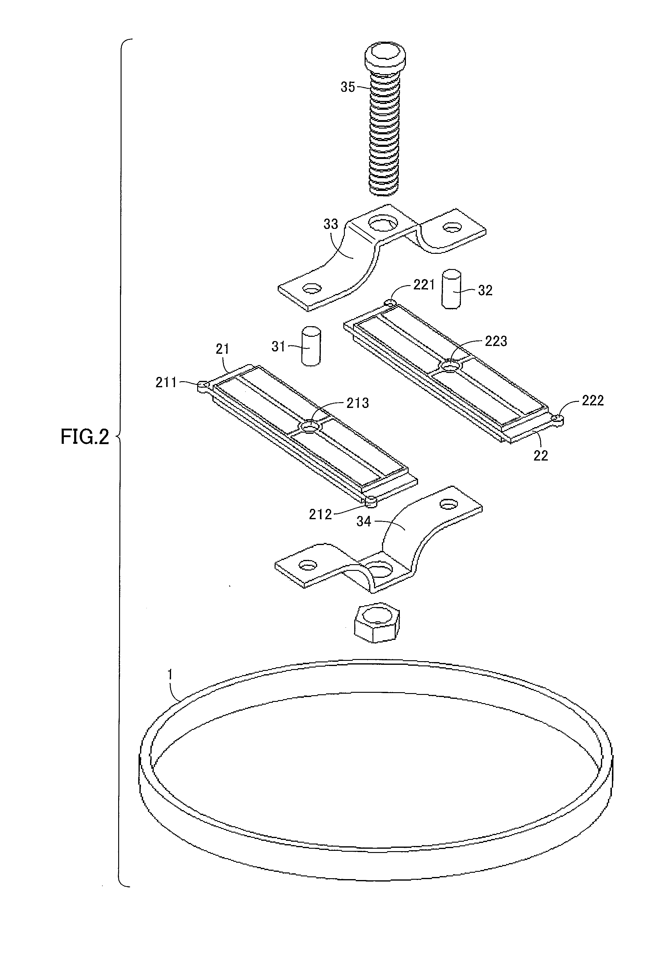
[0059]A configuration of an ultrasonic motor of a first embodiment will be described with reference to FIGS. 1 to 4. Two ultrasonic vibrators 21 and 22 are in internal contact with a cylindrical rotor 1 via contact points 211, 212 (not shown), and contact points 221, 222, respectively.

[0060]Ultrasonic vibrators 21 and 22 are pressed against rotor 1 by means of preload mechanism 3 to be pushed and expanded outward. Ultrasonic vibrator 21 performs an elliptical motion as described with reference to FIG. 16 by receiving the above-mentioned alternating voltages φA, φB with the phases being shifted by 90°.

[0061]Ultrasonic vibrator 22 has a configuration in which electrodes are arranged in mirror symmetry with those of ultrasonic vibrator 21, and performs an elliptical motion as described with reference to FIG. 16 by receiving the above-mentioned alternating voltages 4A, 4B with the phases being shifted by 90°. That is, all contact points in internal contact with rotor 1 perform the ellip...

second embodiment

[0079]A configuration of an ultrasonic motor of a second embodiment will be described with reference to FIGS. 5 to 9. For the sake of clarity, components identical to those of the embodiment described above will be designated by the same reference numerals, and the description thereof will not be repeated.

[0080][Overall Configuration]

[0081]As shown in FIGS. 5 and 6, ultrasonic vibrators 41 and 42 are configured to be pushed and expanded toward the outside of rotor 1 by means of a pantograph type preload mechanism 43 having projections 431, and are in internal contact with rotor 1. As for the rest, ultrasonic vibrators 41 and 42 are configured in the same way as those in the first embodiment.

[0082][Ultrasonic Vibrators]

[0083]Since ultrasonic vibrators 41 and 42 are in mirror symmetry with each other, only ultrasonic vibrator 42 will be described below with reference to FIG. 7. Ultrasonic vibrator 42 has a recess 421 at a central portion of a side surface thereof. This can determine t...


PUM


Abstract

An ultrasonic motor has a cylindrical rotor for performing a mechanical output, a plurality of ultrasonic vibrators each having two points in internal contact with the rotor, and a preload mechanism for pressing the ultrasonic vibrators from an inside toward an outside of the rotor, and the ultrasonic vibrators are provided to be rotatable relative to the preload mechanism. With this configuration, an internal contact type ultrasonic motor capable of performing efficient drive by using a plurality of ultrasonic vibrators each in contact with a cylindrical rotor at two points and allowing contact at all contact points without requiring a high machining accuracy can be provided.

Description

[0001]This nonprovisional application is based on Japanese Patent Application No. 2008-124843 filed on May 12, 2008 with the Japan Patent Office, the entire contents of which are hereby incorporated by reference.BACKGROUND OF THE INVENTION[0002]1. Field of the Invention[0003]The present invention relates to an ultrasonic motor.[0004]2. Description of the Background Art[0005]Piezoelectric elements made of such as PZT (Lead Zirconate Titanate) can store large mechanical energy per unit volume, and small-sized high-power actuators using the same have been put to practical use. These are generally called as ultrasonic motors. In the following, a basic operation of a resonance ultrasonic motor will be described.[0006]Ultrasonic motors of a type obtaining an elliptical motion by exciting a plurality of vibration modes having an identical resonance frequency in a piezoelectric element and moving a driven body by friction have been under study for a long time. For example, FIG. 10 shows an ...

Claims


Application Information

Patent Timeline
Patent Type & Authority Applications(United States)
IPC IPC(8): H02N2/12
CPCH02N2/004H02N2/103H02N2/0055
Inventor HAMAMOTO, MASAKIKOTANI, TERUHISA
Owner SHARP KK
Why Eureka
Try Eureka