

Forming method of tooth trace of gear
- Summary
- Abstract
- Description
- Claims
- Application Information
AI Technical Summary
Benefits of technology
Problems solved by technology
Method used
Image

Examples
second embodiment
[0044]FIG. 6 shows an induction hardening unit 11 as a surface-treatment unit used in the The induction hardening unit 11 has a circular induction heating coil 12 and a supporting tool 13. The supporting tool 13 has a cylindrical part 14 whose diameter is substantially the same as the inside surface of the large opening 56 of the preformed main part 52a of the preformed gear 51a. A plate-like supporting part 15 extends serially from the cylindrical part 14. A shaft 16 protrudes from a surface of the supporting part 15 on a side opposite to the cylindrical part 14. The shaft 16 is connected to a controlling unit not shown.
[0045] A method of forming (adjusting) the tooth flank(s) of the tooth part(s) 53 of the internal gear 51 by using the induction hardening unit 11 is explained with reference to FIG. 6.
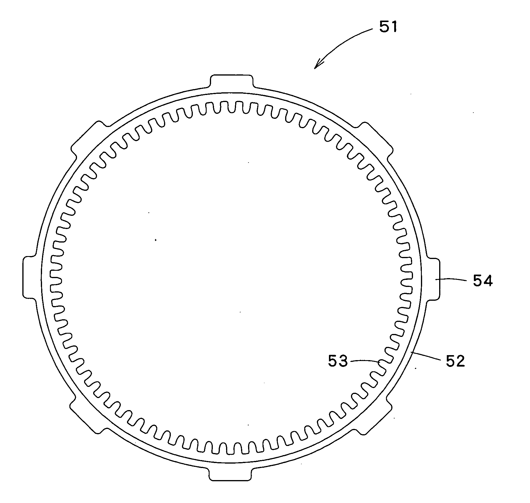
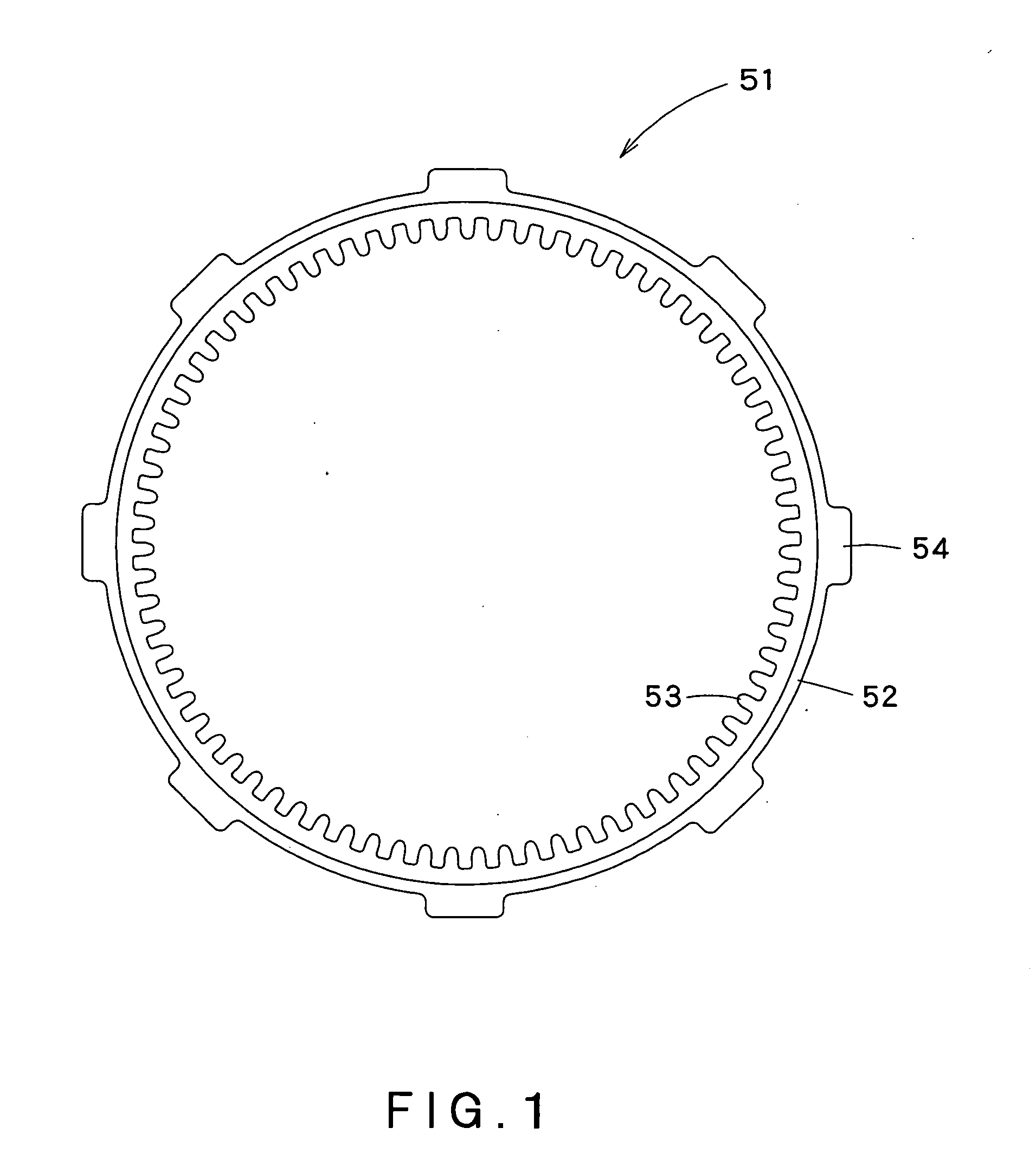
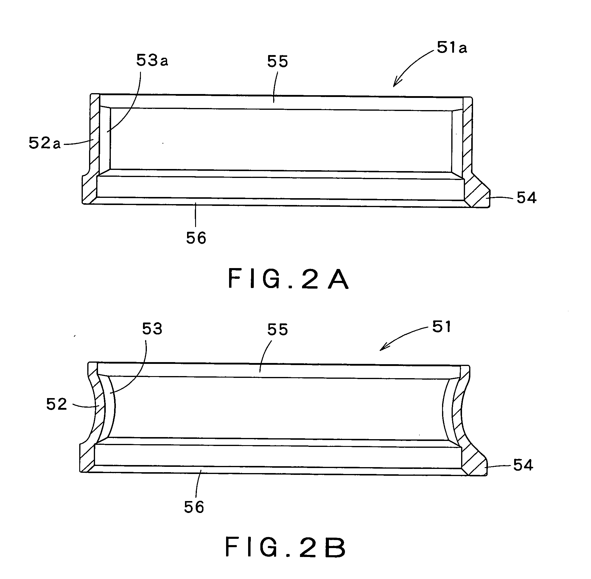
[0046] At first, as shown in FIG. 2A, the preformed gear 51a is prepared, in which the preformed tooth part 53a having the flat tooth flank of the uniform thickness in the tooth tra...
third embodiment
[0050]FIG. 7 shows a shot peening unit 21 as a surface-treatment unit used in the The shot peening unit 21 has a nozzle head 22 and a supporting tool 23 for supporting the preformed gear 51a′. The supporting tool 23 has an upper cover 26 and a lower cover 29. The upper cover 26 has an upper cup portion 24 of a cup shape having an inside surface of substantially the same diameter as the outside surface of the preformed gear 51a′ on the side of the large opening 56, and an upper shaft 25 extending upward from the upper cup portion 24. The lower cover 29 has a lower cup portion 27 of a cup shape having an inside surface of substantially the same diameter as the outside surface of the preformed gear 51a′ on the side of the small opening 55, and a lower shaft 28 extending downward from the lower cup portion 27. The upper shaft 25 of the upper cover 26 and the lower shaft 28 of the lower cover 29 are connected to a controlling unit not shown. A predetermined gap is formed between the upp...
PUM
| Property | Measurement | Unit |
|---|---|---|
| Thickness | aaaaa | aaaaa |
Abstract
Description
Claims
Application Information