
Scanning backlight color control

a backlight and color control technology, applied in the field of panel display backlights, can solve the problems of not being widely used in high-end applications, introducing more unwanted artifacts, and mixing lengths that are not enough to achieve the required color uniformity, etc., to achieve uniform colour in the different sections, maintain the effect of accuracy and low cos

Inactive Publication Date: 2009-11-12
BARCO NV
View PDF4 Cites 69 Cited by
  • Summary
  • Abstract
  • Description
  • Claims
  • Application Information

AI Technical Summary

Benefits of technology

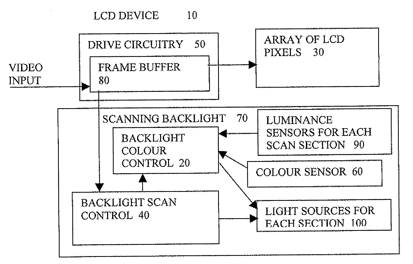
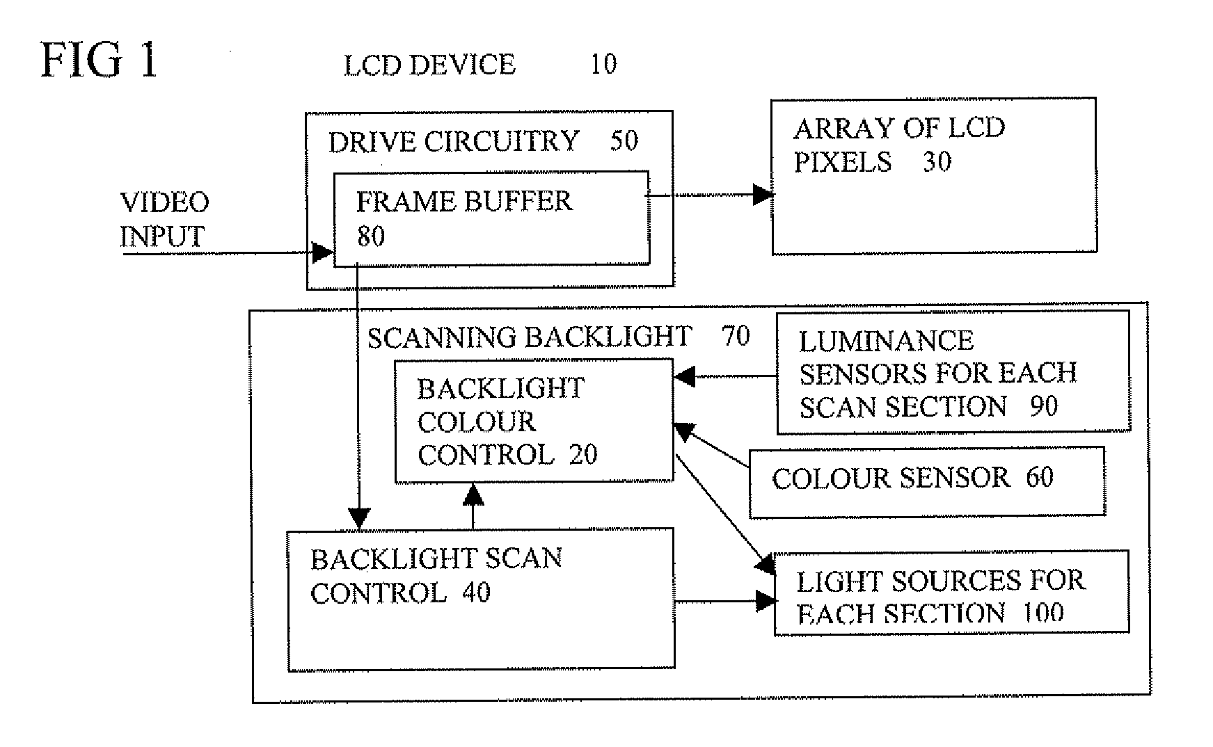
[0009]This combination can enable the colour output to be maintained more accurately than relying on sensing luminance values of individual colour sources, which gives little indication of spectral shift for example. It is particularly useful to be able to accomplish this where there are sections separately illuminated, without needing an external spectrometer. As the sections are separately illuminated, the uniformity of colour in the different sections can be controlled as desired. Such control can enable the specifications of any parts used to illuminate the sections to be relaxed, such as temperature and aging specifications, which can keep the costs lower. This becomes more important as the number of sections increases. Furthermore it can help enable real time measurement of individual LED-groups without hindering display function. Embodiments of the invention can have any other features added, some such additional features are set out in dependent claims and described in more detail below.

Problems solved by technology

This mixing length is hardly sufficient to arrive at the required color uniformity.
But such backlight scanning has not been widely used in high end applications as it increases complexity, can introduce more unwanted artifacts and reduces dimming range.
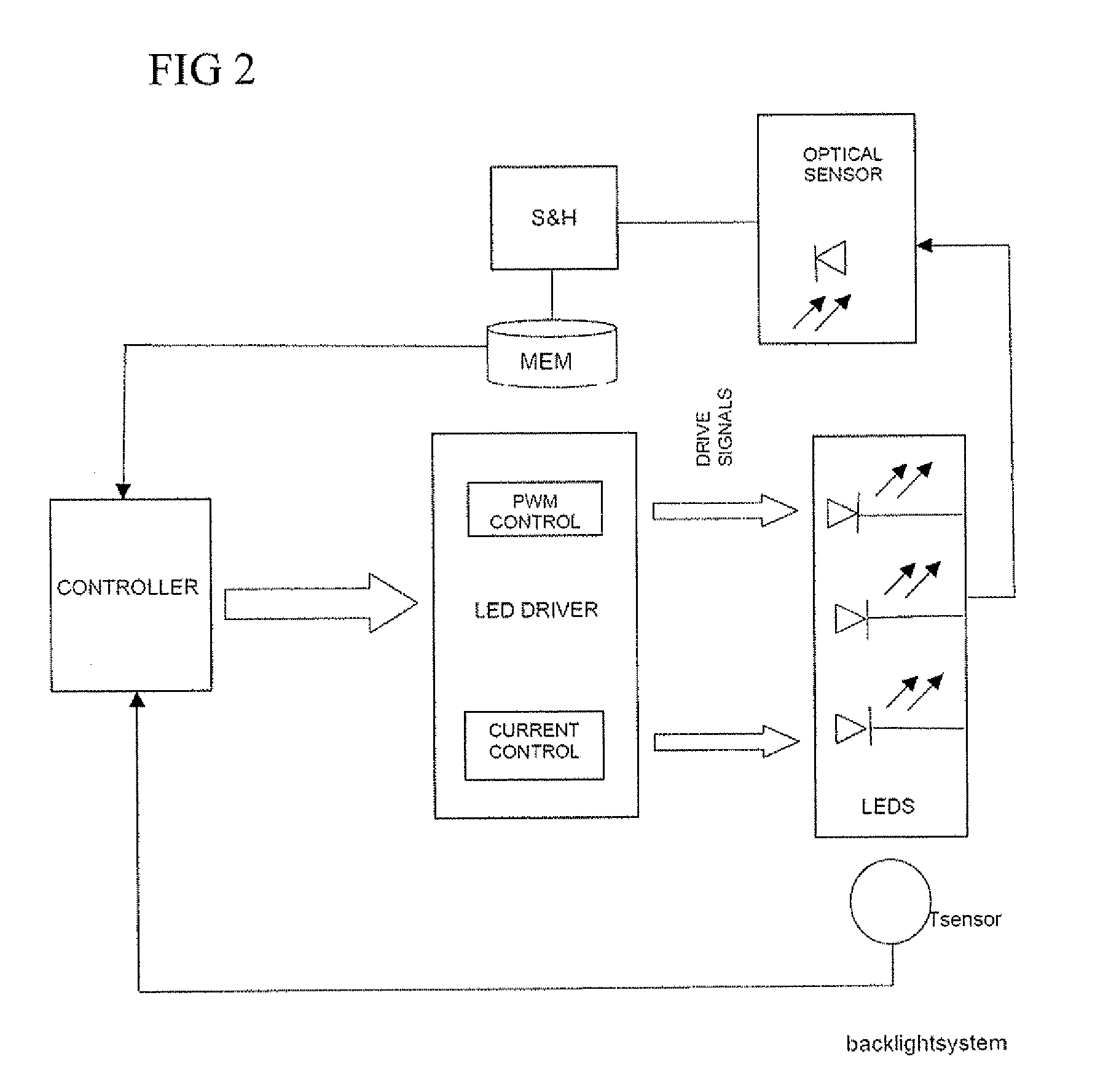
Consequently, conventional LED based backlights and others do not reliably maintain a desired intensity and / or colour during their lifetime.
This results in very slow response times and if high dimming ratio is required also results in high resolution and expensive A / D converters being required.

Method used


Image

  • Scanning backlight color control
  • Scanning backlight color control
  • Scanning backlight color control

Examples


Embodiment Construction

[0018]The present invention will be described with respect to particular embodiments and with reference to certain drawings but the invention is not limited thereto but only by the claims. The drawings described are only schematic and are non-limiting. In the drawings, the size of some of the elements may be exaggerated and not drawn on scale for illustrative purposes. Where the term “comprising” is used in the present description and claims, it does not exclude other elements or steps. Where an indefinite or definite article is used when referring to a singular noun e.g. “a” or “an”, “the”, this includes a plural of that noun unless something else is specifically stated.

[0019]The term “comprising”, used in the claims, should not be interpreted as being restricted to the means listed thereafter; it does not exclude other elements or steps. Thus, the scope of the expression “a device comprising means A and B” should not be limited to devices consisting only of components A and B. It ...


PUM


Abstract

A scanning backlight (70) for a display, the backlight having a number of sections separately illuminated, a controller (20) to control the illuminating of the different sections at different times, and to control relative luminance levels of the different sections, and the backlight having a sensor (60) to detect a spectrum of the lighting, the controller being arranged to control a color of the illuminations of the different sections according to the detected spectrum. This combination can enable the color output to be maintained accurately without needing an external spectrometer, and control the uniformity of color in the different sections. This control can enable the specifications of any parts used to illuminate the sections to be relaxed, such as temperature and aging specifications, to keep the costs lower.

Description

FIELD OF THE INVENTION[0001]This invention relates to backlights for panel displays such as liquid crystal devices and to corresponding systems and methods.DESCRIPTION OF THE RELATED ART[0002]A reference monitor needs to have a very high luminance and color uniformity over the entire screen area, as well as a wide, controllable and stable color gamut (well defined color triangle). The last requirement leads to the use of R-G-B LED light sources in the backlight.[0003]But in order to get a uniform white light output over the entire screen starting from the discrete red, green and blue point-like light sources, one has to incorporate long optical mixing lengths. This leads to a display with a large depth. In a practical situation not more than approximately 50 mm is available for the complete backlight assembly, so this is also the largest available mixing length. This mixing length is hardly sufficient to arrive at the required color uniformity.[0004]Another specification of a refere...

Claims


Application Information

Patent Timeline
IPC IPC(8): G09G3/36
CPCG09G3/3413G09G3/342G09G2360/145G09G2320/0233G09G2320/0666G09G2310/024
Inventor DECLERCQ, BJORNDEBONNET, JEROENDE PAEPE, KRISTIAAN
Owner BARCO NV
Learn More