Display using bidirectionally scanned linear modulator

a linear modulator and display technology, applied in the field of display apparatus using linear light modulators, can solve the problems of reducing the available light output, limiting the light efficiency that can be obtained, and inherent limitations of display solutions that use these devices, so as to improve the effective duty cycle, reduce complexity, and add brightness

Active Publication Date: 2009-11-12
IMAX THEATERS INT
View PDF24 Cites 51 Cited by
  • Summary
  • Abstract
  • Description
  • Claims
  • Application Information

AI Technical Summary

Benefits of technology

[0025]It is an advantage of the present invention that it can improve the effective duty cycle over conventional methods for stereoscopic display, yielding added brightness.
[0026]It is an advantage of the present invention that it provides stereoscopic projection using three or more solid-state light sources with reduced complexity and reduced optical alignment requirements over conventional designs.

Problems solved by technology

However, there are some inherent limitations for display solutions that use these devices.
This reduces the available light output and limits the light efficiencies that can be obtained.
Bidirectional scanning for 2-D imaging also sacrifices image resolution somewhat in practice, particularly for displays having high resolution.
Although such two-projector designs have successfully shown the feasibility and enhanced imaging capabilities afforded by stereoscopic imaging systems, these systems are expensive, require precision alignment to each other, and impose some additional requirements on theater design and layout.
Stereoscopic solutions have been implemented using a single projector, but generally at the cost of reduced light output.
Conventional solutions such as doubling the number of light sources or doubling the number of light modulators are feasible, but are also expensive and impractical.
The conventional modulation scheme that has been used for 2-D imaging does not easily adapt to the requirements of stereoscopic or 3-D (three-dimensional) imaging.
Simply doubling frame refresh rates from 60 Hz to 120 Hz and alternating left- and right-eye image sub-frames does not appear to be a desirable solution.
Higher frame rates place demands on scanning devices, such as a galvanometric scanner, that can be difficult to meet.
In the face of these difficulties, linear light modulators seem unlikely contenders for the stereoscopic imaging market.
The excessive cost of providing multiple projector devices, registered to each other for independently providing left- and right-eye images, and the complex data paths, alignment, and timing that would be required to coordinate and project left- and right-eye modulated light make dual-projector solutions unattractive and well out of the price range of lower-cost equipment.
Other conventional approaches to stereoscopic display using a single projector have required considerable complexity and, due at least in part to disappointing brightness in the displayed output, may not yield pleasing results in the final image that is displayed.

Method used


Image

  • Display using bidirectionally scanned linear modulator
  • Display using bidirectionally scanned linear modulator
  • Display using bidirectionally scanned linear modulator

Examples


Embodiment Construction

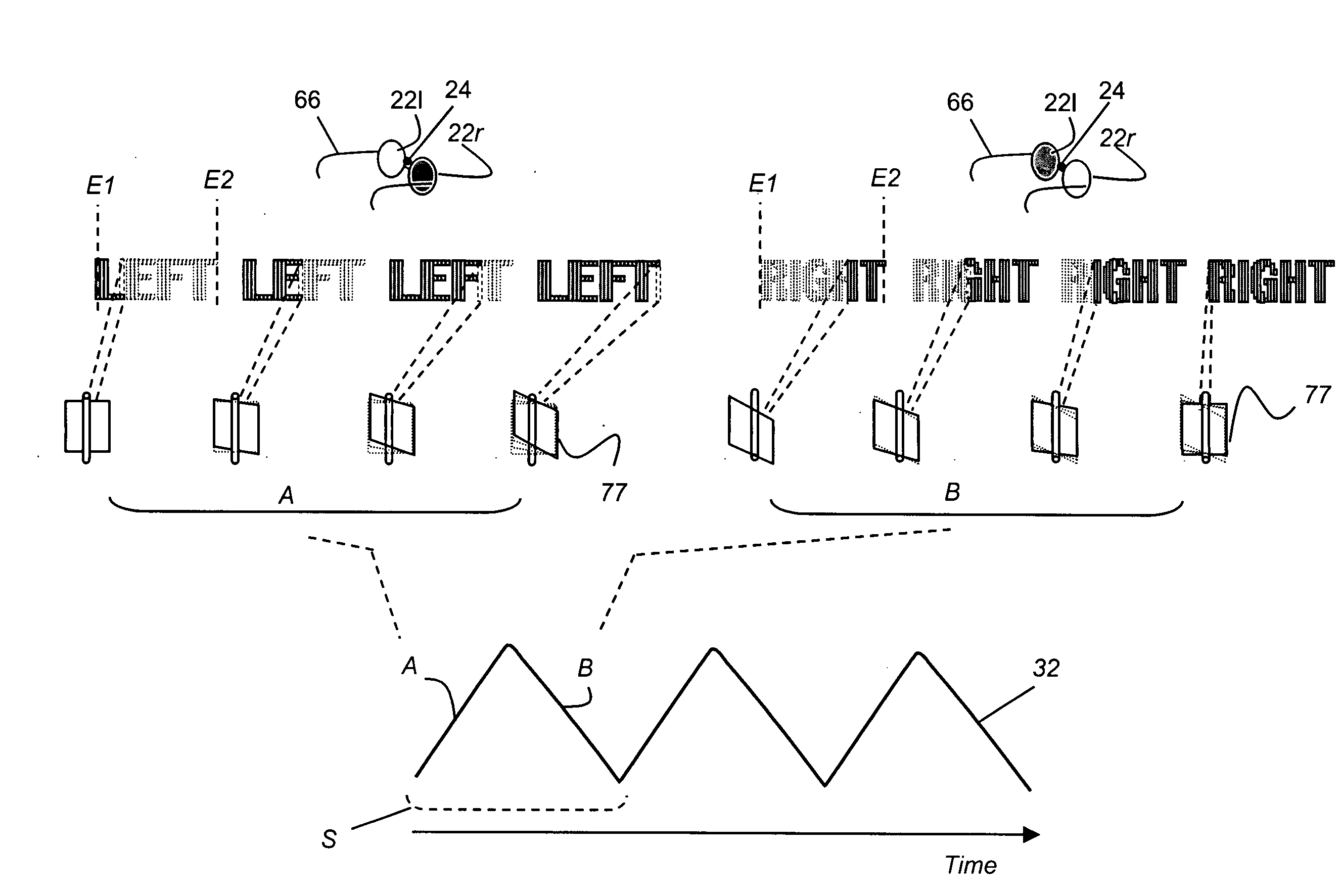
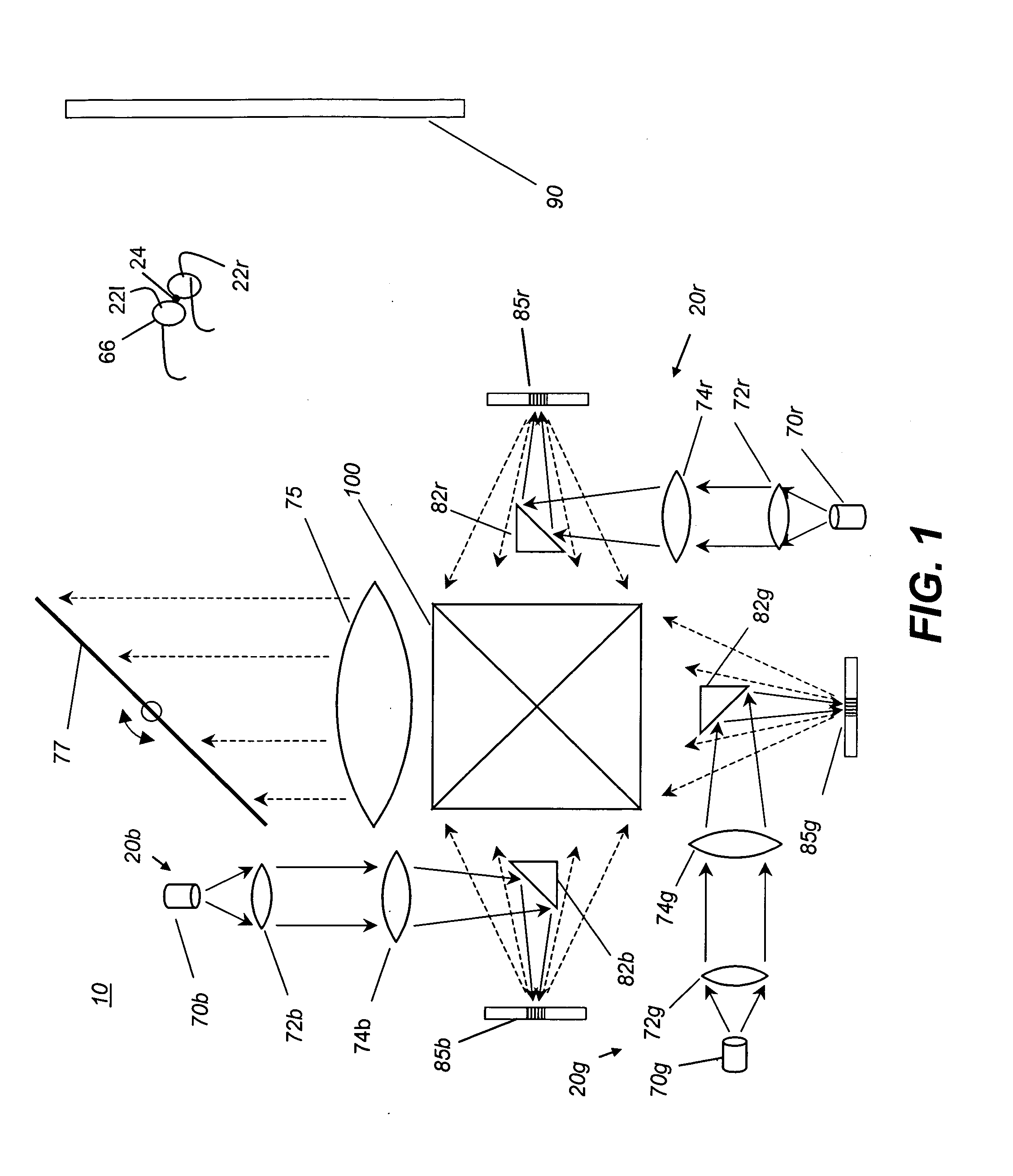
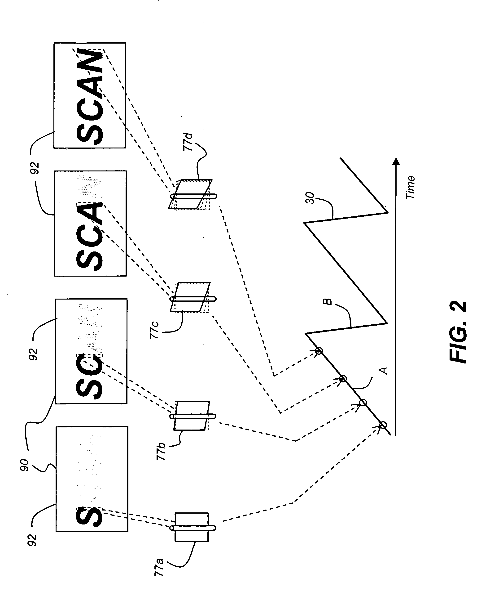
[0046]The present description is directed in particular to elements forming part of, or cooperating more directly with, apparatus in accordance with the invention. It is to be understood that elements not specifically shown or described may take various forms well known to those skilled in the art. Figures shown and described herein are provided in order to illustrate key principles of operation of the present invention and are not drawn with intent to show actual size or scale. Some exaggeration may be necessary in order to emphasize relative spatial relationships or principles of operation.

[0047]In the following disclosure, the phrase “left-eye image” denotes the image formed by a display apparatus and intended for viewing by the left eye of the viewer. Likewise, the phrase “right-eye image” refers to the separate image that is intended for viewing from the right eye of the viewer. The terms “stereoscopic” and “3-D” are considered to be equivalent.

[0048]In the context of the prese...


PUM


Abstract

A method for forming a stereoscopic image forms separate left-eye and right-eye images in a repeated cycle that forms the left-eye image by providing data for lines of the left-eye image, ordered in sequence from a first to a second edge of an image frame, then forms successive lines of modulated light according to the ordered sequence by progressively scanning lines of modulated light across a display surface by rotating a scanning element forward from a first to a second position. The right-eye image is formed by providing data for lines of the right-eye image, ordered in sequence from the second to the first edge of the image frame and forming successive lines of modulated light, progressively scanning the lines of modulated light across the display surface by rotating the scanning element in reverse from the second to the first position. The left-eye image is distinguished from the right-eye image.

Description

CROSS REFERENCE TO RELATED APPLICATIONS[0001]Reference is made to commonly-assigned copending U.S. patent application Ser. No. 11 / 950,488, filed Dec. 5, 2007, entitled DISPLAY APPARATUS USING BILINEAR ELECTROMECHANICAL MODULATOR, by Agostinelli et al.; and U.S. patent application Ser. No. 12 / 047,605, filed Mar. 13, 2008, entitled STEREOSCOPIC DISPLAY USING MULTILINEAR ELECTROMECHANICAL MODULATOR, by Marcus et al., the disclosures of which are incorporated herein.FIELD OF THE INVENTION[0002]This invention generally relates to display apparatus using linear light modulators and more particularly relates to a display apparatus and method for forming stereoscopic images by scanning modulated light, one line at a time per color, across a display surface.BACKGROUND OF THE INVENTION[0003]Linear light modulators form images by a rapid, repeated sequence in which each single line of the image is separately formed and is directed to a screen or other display surface by reflection, or other ty...

Claims


Application Information

Patent Timeline
Patent Type & Authority Applications(United States)
IPC IPC(8): H04N13/04G02B27/22G02B27/26G03B21/28G02B30/25H04N13/363
CPCG02B27/2228G02B27/2271G02B27/26H04N13/0431H04N3/10H04N13/0438H04N13/0454H04N13/0459H04N13/0497H04N13/0434H04N13/337H04N13/341H04N13/334H04N13/363H04N13/359H04N13/398G02B30/50G02B30/34G02B30/25
Inventor MARCUS, MICHAEL A.AGOSTINELLI, JOHN A.KOWARZ, MAREK W.
Owner IMAX THEATERS INT
Why Eureka
Try Eureka