
Lens cleaning warning system and method

a technology of cleaning warning and lens, applied in the field of lens cleaning warning system and method, can solve the problems of image appearance foggy, cellular telephone camera lens easily being covered with contaminants,

Active Publication Date: 2009-11-12
APTINA IMAGING CORP
View PDF12 Cites 80 Cited by
  • Summary
  • Abstract
  • Description
  • Claims
  • Application Information

AI Technical Summary

Problems solved by technology

Lens flare is a generally undesirable feature of some images, which causes these images to appear foggy.
This foggy appearance may occur when, for example, light incident on individual pixels in an image sensor is scattered before it reaches the sensor, spreading the light amongst all or many of the pixels in the image sensor.
Lens flare has several known causes, among which may include oils, dirt, finger prints, lint, dust and / or other contaminants on the lens of the camera which includes the image sensor.
Due to the lack of lens cover or, alternatively, to the user sliding his or her fingers in the vicinity of the lens to cover and uncover the lens, cellular telephone camera lenses may easily become covered with contaminants (e.g., oils, finger prints, etc.).
Also, when a user places the camera in his or her pocket, purse, or other container or leaves the camera out for an extended period of time, the lens may become covered with contaminants (e.g., dirt, lint, dust, etc.).
While not as prevalent a problem for non-phone digital cameras, lenses on such cameras may become contaminated as well.
Because images produced by a camera appear foggy when its lens is contaminated, the user will likely notice that the camera is not producing quality images.
The defects in the image produced by the imager through a contaminated lens are commonly called “lens flare.” Many users, however, will not know that the unsatisfactory images are caused by contaminants on the lens.
Further, even if the user does know that such unsatisfactory images may be caused by contaminants on the lens, a user looking through the view finder (a different lens) or the preview screen (which is often too small to see the image clearly) may not notice that the lens is contaminated before he or she takes the picture.
Accordingly, the user may attribute the poor quality of the images to the quality of his or her camera instead of taking appropriate steps to clean the lens.

Method used


Image

  • Lens cleaning warning system and method
  • Lens cleaning warning system and method
  • Lens cleaning warning system and method

Examples


Embodiment Construction

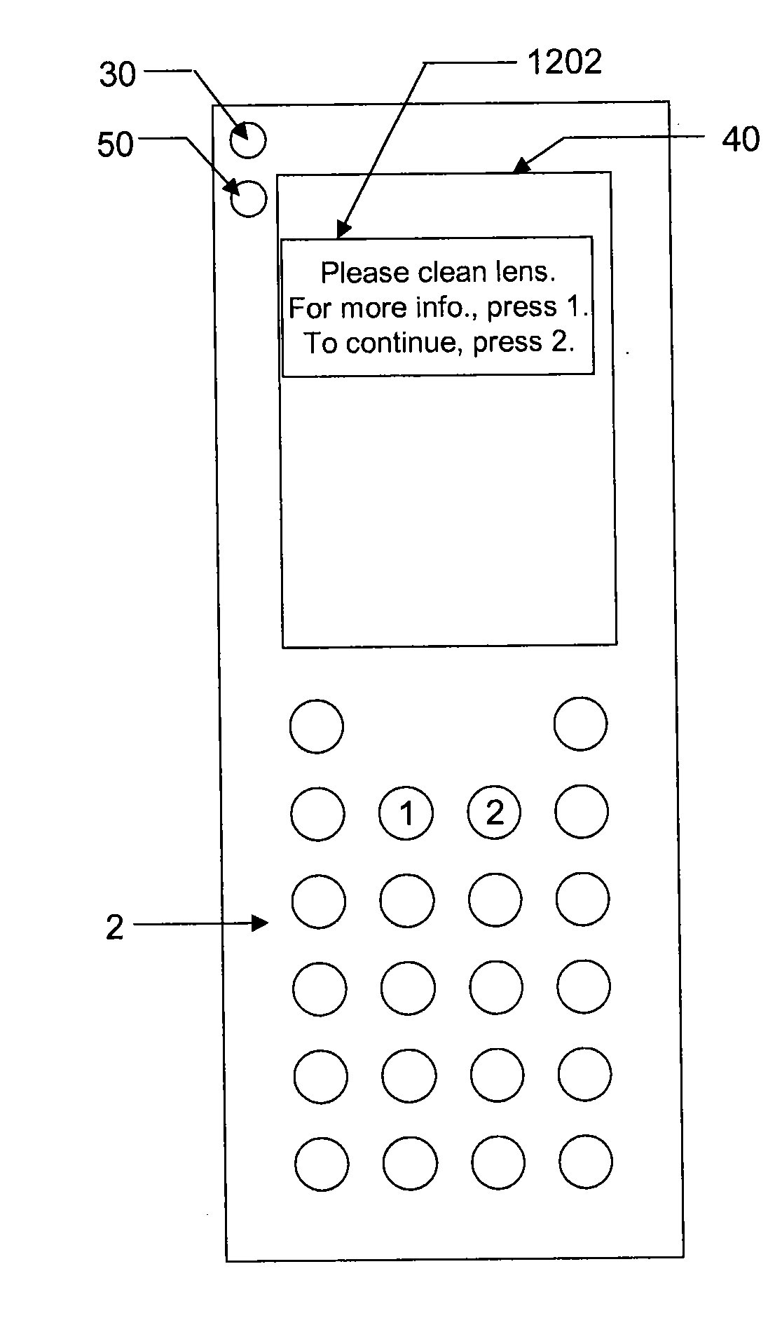
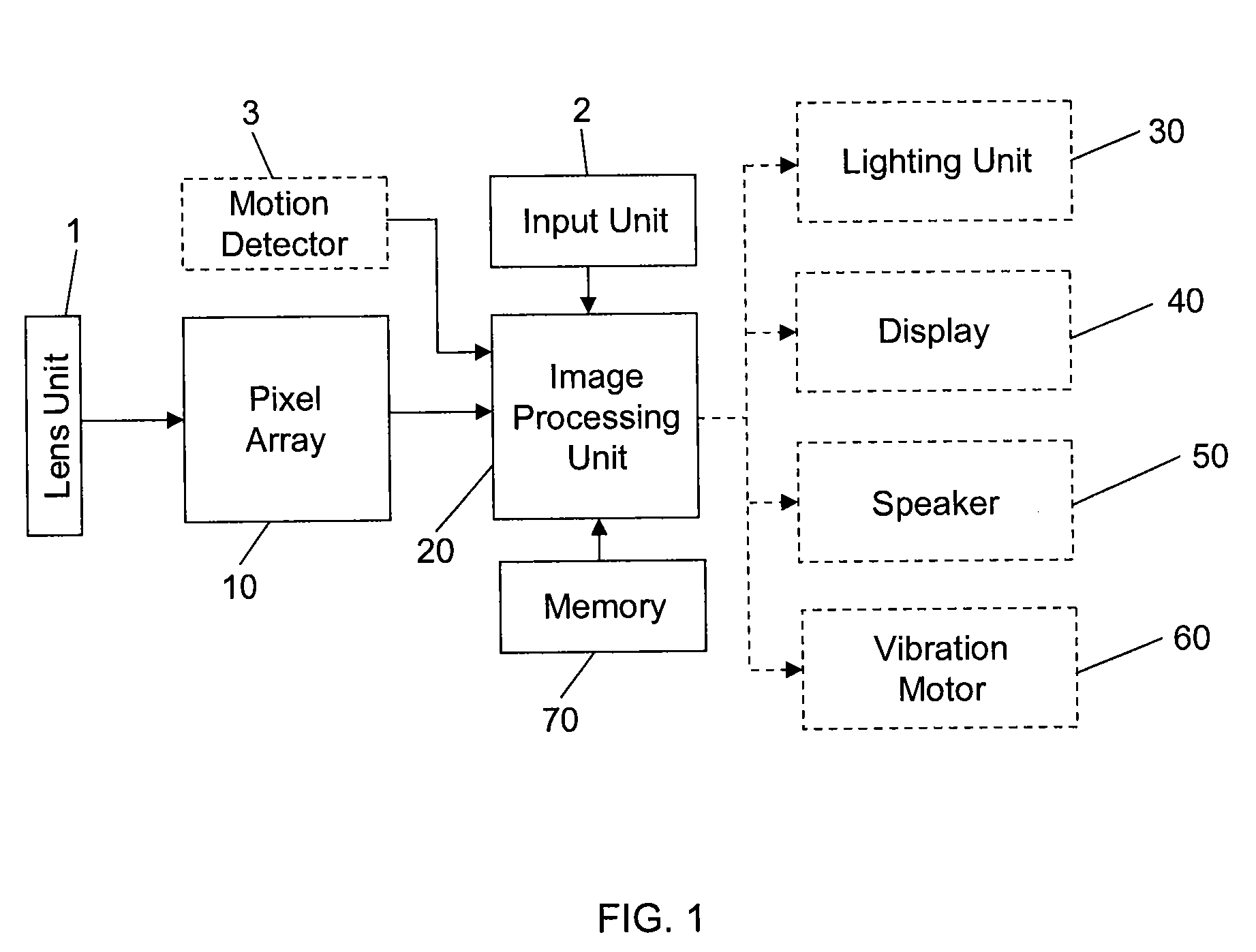
[0017]FIG. 1 is a block diagram of an embodiment of a system for warning that a camera lens is contaminated. As shown, the system includes a lens unit 1, an optional motion detector 3, a pixel array 10, an image processing unit 20, a memory 70, an input unit 2 for allowing a user to interact with the image processing unit 20, and one or more of a lighting unit 30, a display 40, a speaker 50 and a vibration motor 60. In operation, the lens unit 1 may focus a scene within its field of view onto pixel array 10. When the system is on and is in camera mode, the pixel array 10 continually produces signals representing the scene(s) focused onto it. The signals are read out from the array 10 using readout circuitry (not shown) and processed using the image processing unit 20. The processing unit 20 may be configured as hardware or may be configured to process software stored in memory 70.

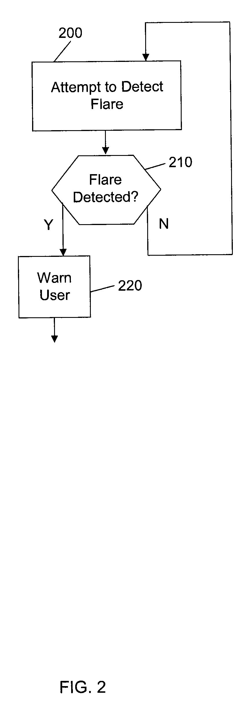
[0018]FIG. 2 is a flow chart showing steps in an embodiment of image processing which may be carried out...


PUM


Abstract

Lens cleaning warning systems and methods. A system includes an image processing unit configured to analyze image data to determine whether the image data indicates lens flare and, if so, provide an indication to the user that the lens is contaminated.

Description

BACKGROUND OF THE INVENTION[0001]Lens flare is a generally undesirable feature of some images, which causes these images to appear foggy. This foggy appearance may occur when, for example, light incident on individual pixels in an image sensor is scattered before it reaches the sensor, spreading the light amongst all or many of the pixels in the image sensor. Lens flare has several known causes, among which may include oils, dirt, finger prints, lint, dust and / or other contaminants on the lens of the camera which includes the image sensor.[0002]Lenses on conventional cellular telephone cameras do not have lens covers or, if they do, the lens covers are slid by a user's fingers to cover or uncover the lens. Due to the lack of lens cover or, alternatively, to the user sliding his or her fingers in the vicinity of the lens to cover and uncover the lens, cellular telephone camera lenses may easily become covered with contaminants (e.g., oils, finger prints, etc.). Also, when a user plac...

Claims


Application Information

Patent Timeline
IPC IPC(8): H04N5/228G06K9/40
CPCG06T7/0002H04N5/3572G06T2207/30168G06T7/0085G06T7/13H04N23/634H04N25/61
Inventor DENG, YININGPOPE, DAVID
Owner APTINA IMAGING CORP
Learn More