Image processing apparatus

a technology of image processing and processing apparatus, which is applied in the direction of polarising elements, television system scanning details, television systems, etc., can solve the problems of not only bulky sensor or system, but also impose various restrictions, and the basic performance of the imaging device would decline too much to maintain the minimum required level,

Active Publication Date: 2009-11-12
PANASONIC CORP
View PDF7 Cites 59 Cited by
  • Summary
  • Abstract
  • Description
  • Claims
  • Application Information

AI Technical Summary

Benefits of technology

[0036]According to the present invention, multiple types of polarizer units are used in combination with a pixel arrangement of a color mosaic filter, and therefore, information about a color intensity and information about polarization can be obtained and processed at the same time.

Problems solved by technology

However, if the size of an optical system or an image capture device were reduced significantly, then the basic performance of the imaging device would decline too much to maintain the minimum required level in terms of sensitivity or diffraction limit of lens.
However, such a sensor or system is not just bulky but also imposes various restrictions.
Besides, such a sensor or system cannot be used unless the object is a solid and bright diffusive object.
Under such a restriction, the sensor or system cannot be used to shoot an object located at a distance outdoors or take a close up photo of a person with his or her hair and clothes shot as beautifully as possible.
However, this camera cannot obtain a single piece of polarization information until several frames are shot with the polarization main axes of the polarizer changed by applying a voltage to the liquid crystal layer.
In other words, these two images cannot be obtained at the same time.
However, since a difference between two different polarization pixels is simply calculated, information about the degree of partial polarization of the object cannot be obtained perfectly.Patent Document No. 1: Japanese Patent Application Laid-Open Publication No. 2006-254331Non-Patent Document No. 1: Lawrence B. Wolff, “Polarization Vision: A New Sensory Approach to Image Understanding”, Image and Vision Computing 15 (1997), pp.

Method used


Image

  • Image processing apparatus
  • Image processing apparatus
  • Image processing apparatus

Examples


embodiment 1

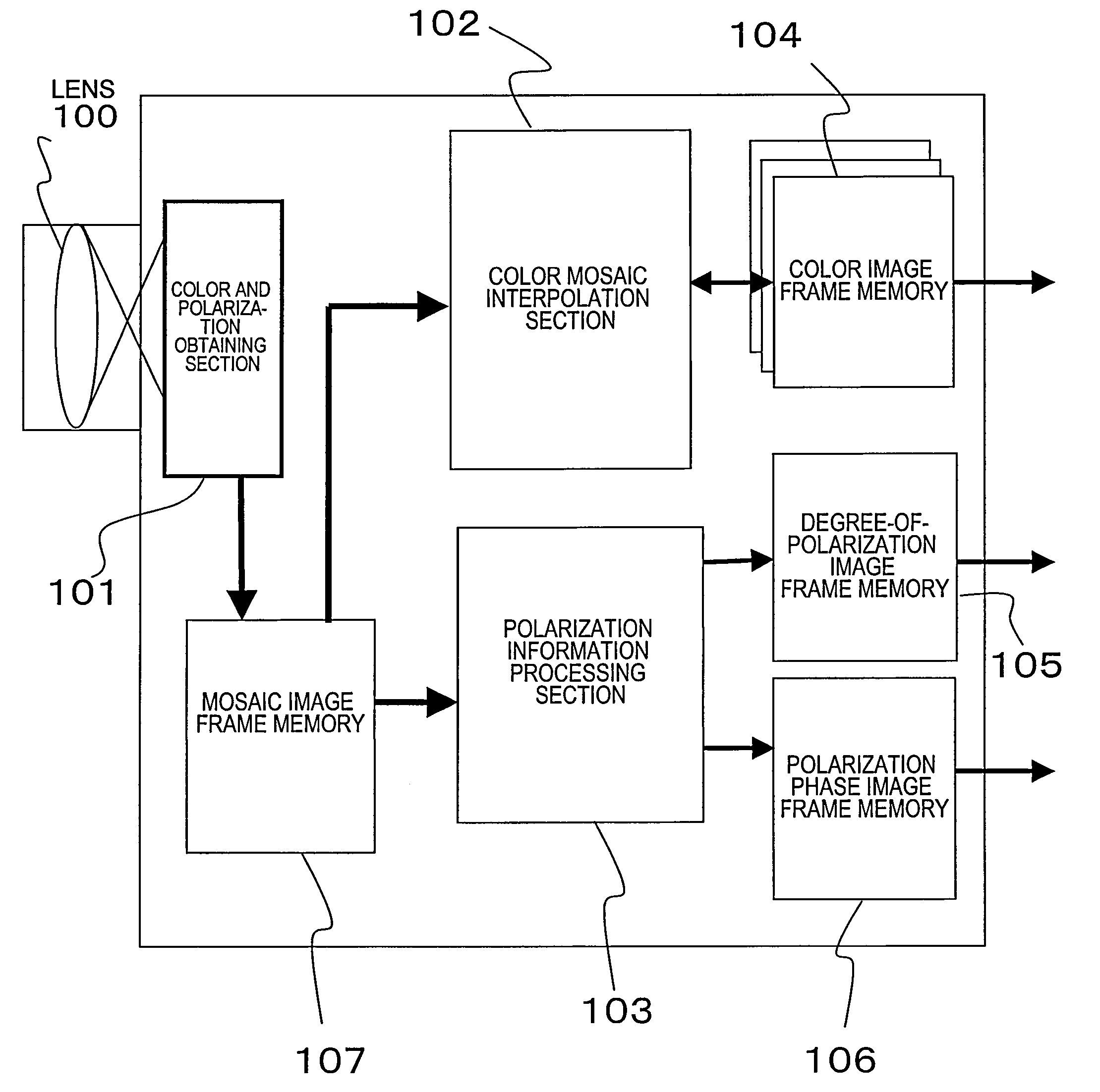
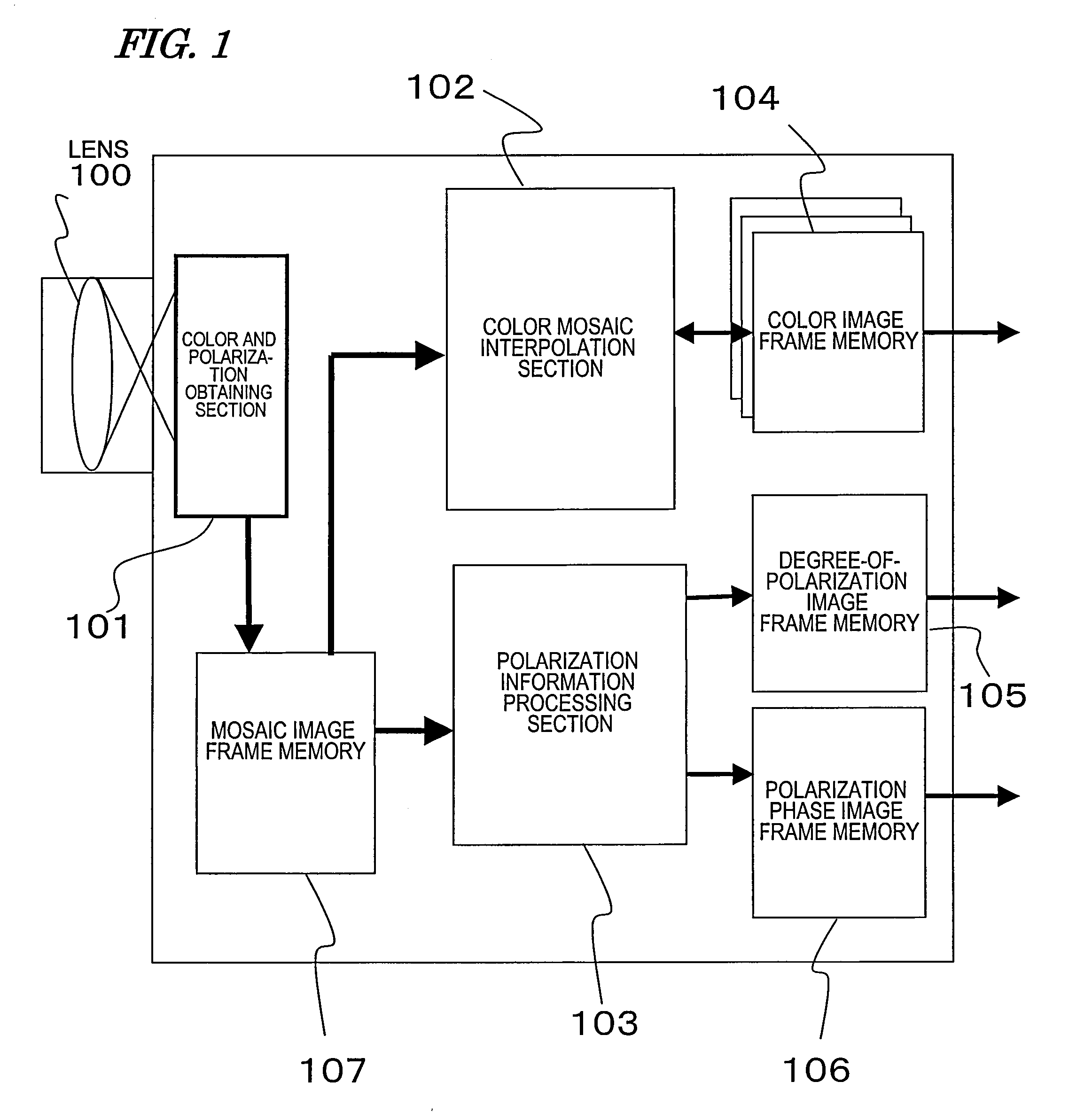
[0087]FIG. 1 is a block diagram illustrating a basic configuration that applies to every preferred embodiment of the present invention to be described herein. The apparatus of this preferred embodiment obtains not only color image information from an object in real time but also polarized image information at the same time, and outputs those pieces of information as two different types of polarized images (i.e., a degree-of-polarization image ρ and a polarization phase image φ). Each of the degree-of-polarization image ρ and the polarization phase image φ could be either a still picture or a moving picture.

[0088]After having passed through the lens 100 shown in FIG. 1, the incident light enters a color and polarization obtaining section 101. From this incident light, the color and polarization obtaining section 101 can obtain data about a color moving picture and data about a polarization information image at the same time. The data about the color mosaic image is output from the co...

embodiment 2

[0156]Hereinafter, a second preferred embodiment of an image processing apparatus according to the present invention will be described.

[0157]The basic configuration of this preferred embodiment is also as shown in the block diagram of FIG. 1. That is why this preferred embodiment will also be described with reference to FIG. 1 when necessary. The image processing apparatus of this preferred embodiment is characterized in that polarizer units that form the patterned polarizer are provided for all of R, G and B pixels.

[0158]FIG. 16(a) illustrates a pixel arrangement for the color and polarization obtaining section 101 of this preferred embodiment. Unlike the pixel arrangement of the first preferred embodiment described above, polarizer units are provided for not only G pixels but also R and B pixels as well. In FIG. 16(b), among the R and B pixels that are adjacent to the G pixels, a group of line segments, each connecting a G pixel to another pixel with a polarization main axis that ...

embodiment 3

[0221]Hereinafter, a third preferred embodiment of an image processing apparatus according to the present invention will be described.

[0222]The basic configuration of this preferred embodiment is also as shown in the block diagram of FIG. 1. That is why this preferred embodiment will also be described with reference to FIG. 1 when necessary. The image processing apparatus of this preferred embodiment is characterized in that polarizer units that form the patterned polarizer are provided for either only G and R pixels or only G and B pixels.

[0223]FIG. 25 illustrates a pixel arrangement for the color and polarization obtaining section 101 of this preferred embodiment. This arrangement is based on a Bayer type color mosaic filter. At G pixel locations, arranged are four types of polarization pixels G1 through G4, of which the polarization main axis directions are identified by the numerals “1” through “4”, respectively. The arrangement of those G1 through G4 pixels is the same as the o...


PUM


Abstract

An image processing apparatus according to the present invention includes: a color and polarization obtaining section 101 including a single-chip color image capture device that has a color mosaic filter 201 and a patterned polarizer 202 in which a number of polarizer units, having polarization transmission planes defining mutually different angles, are provided for multiple pixels of the same color (G) in the color mosaic filter 201; a polarization information processing section 103 for approximating, as a sinusoidal function, a relation between the intensities of light rays that have been transmitted through the polarizer units for the G pixels and the angles of the polarization transmission planes of the polarizer units; and a color mosaic interpolation section 103 for generating a color intensity image by performing color intensity interpolation and getting a color intensity that cannot be obtained at a pixel of interest.

Description

TECHNICAL FIELD[0001]The present invention relates to an image processing apparatus that allows the user to obtain both color information and polarization information alike from the object.BACKGROUND ART[0002]Recently, digital movie cameras have advanced so dramatically that it is expected that cellphones with a camera would achieve as high definition as an HDTV in the near future. However, if the size of an optical system or an image capture device were reduced significantly, then the basic performance of the imaging device would decline too much to maintain the minimum required level in terms of sensitivity or diffraction limit of lens. For that reason, such a high-resolution trend should hit a plateau sooner or later. Even so, however, the image quality can still be improved by compensating for the lack of image information of the object by computer graphics type processing. Nevertheless, for that purpose, pieces of physical information, including information about the three-dime...

Claims


Application Information

Patent Timeline
Patent Type & Authority Applications(United States)
IPC IPC(8): H04N5/228H04N5/335G02B5/20G02B5/30H01L27/14H04N5/369H04N9/07
CPCH04N2209/046H04N9/045H04N23/843H04N25/134
Inventor KANAMORI, KATSUHIROSATO
Owner PANASONIC CORP
Why Eureka
Try Eureka