

Surface-area light source device and liquid crystal display device using the same
- Summary
- Abstract
- Description
- Claims
- Application Information
AI Technical Summary
Benefits of technology
Problems solved by technology
Method used
Image

Examples
first preferred embodiment
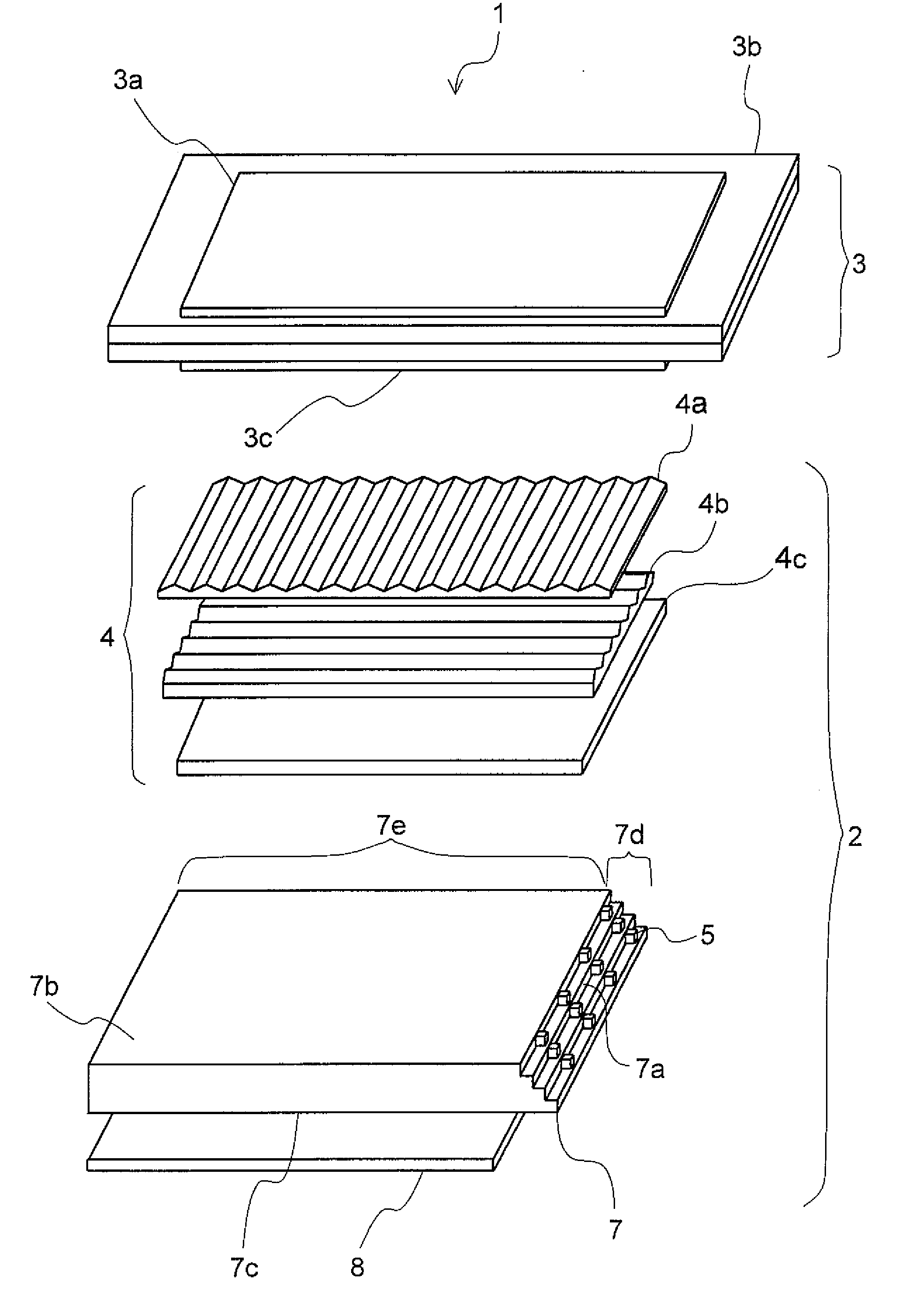
[0045]First, with respect to a liquid crystal display device incorporating a surface-area light source device of a first preferred embodiment of the present invention, a brief description will be given of its operation, along with a brief description of its structure with reference to FIG. 1. FIG. 1 is an exploded perspective view showing the structure of the liquid crystal display device and the surface-area light source device.
[0046]As shown in FIG. 1, the liquid crystal display device 1 includes a liquid crystal display panel 3 and the surface-area light source device 2 that is placed on the rear surface side of the liquid crystal display panel 3.
[0047]The liquid crystal display panel 3 includes a liquid crystal panel 3b having a sandwiched liquid crystal layer (not shown) and polarization plates 3a and 3c that are placed on the top surface side and the bottom surface side of the liquid crystal panel 3b, respectively. The surface-area light source device 2 includes a transparent ...
second preferred embodiment
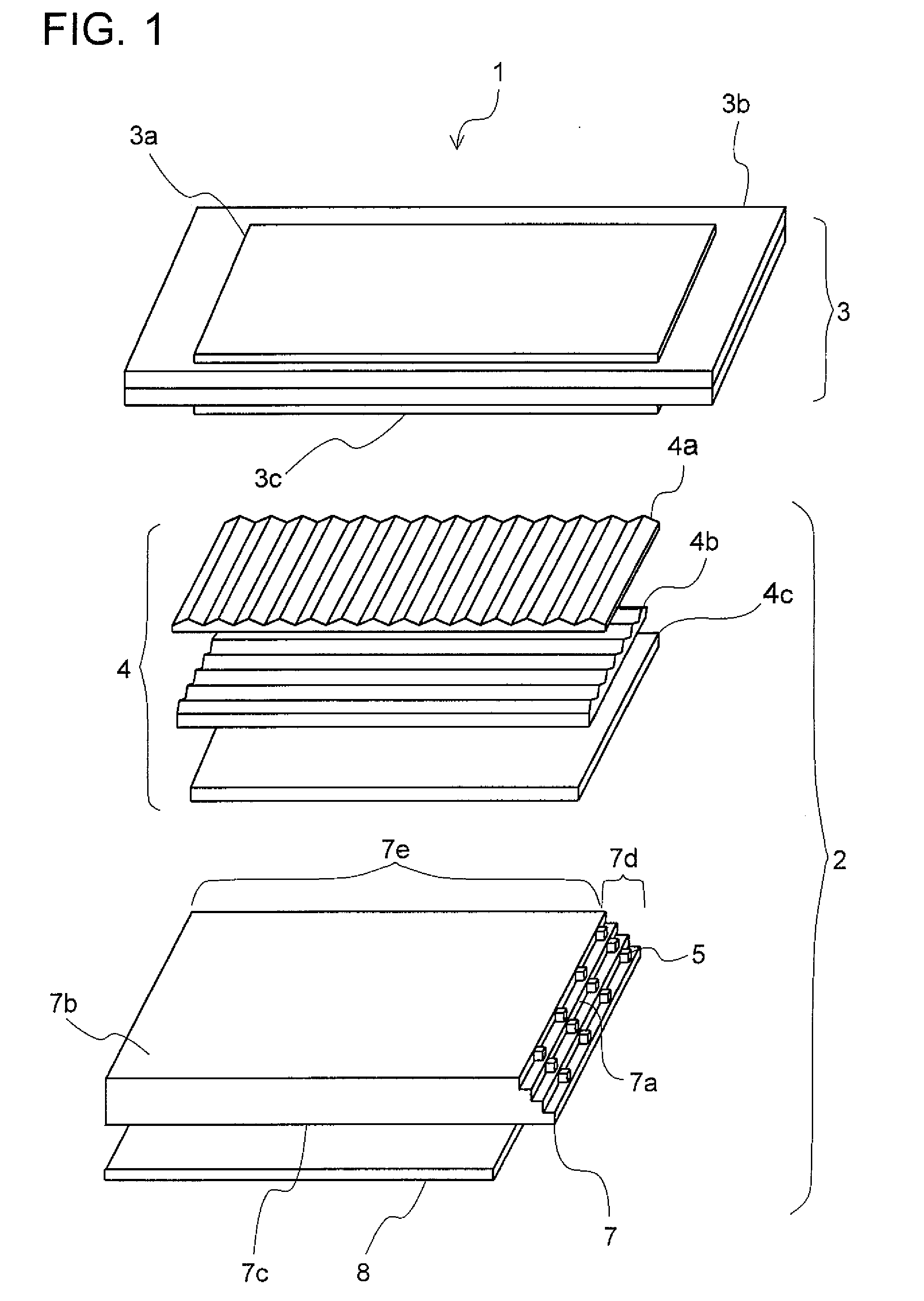
[0062]Next, a description will be given of the structure of a surface-area light source device of a second preferred embodiment of the present invention with reference to FIGS. 3 and 4. FIG. 3 is a perspective view showing a light entrance portion of a light guide plate, and FIG. 4 is a front view showing the light entrance portion of the light guide plate. The liquid crystal display device and the surface-area light source device of this preferred embodiment are structured in the same manner as in the first preferred embodiment, and thus descriptions of them will be omitted.
[0063]As shown in FIGS. 3 and 4, light emitting diodes 5 disposed on a step are disposed such that they are displaced in the direction of a long side of the light entrance side surface 7a (i.e., the direction X in the figures) with respect to light emitting diodes 5 disposed on an adjacent step.
[0064]With the surface-area light source device 2 structured as described above, a dark space between the light emittin...
third preferred embodiment
[0067]Next, a description will be given of the structure of the surface-area light source device of a third preferred embodiment of the present invention with reference to FIGS. 5 and 6. FIG. 5 is a perspective view showing a light entrance portion of a light guide plate, and FIG. 6 is a sectional view taken along line A-A in FIG. 5 showing the light entrance portion of the light guide plate. The liquid crystal display device and the surface-area light source device of this preferred embodiment are structured in the same manner as in the first preferred embodiment, and thus descriptions of them will be omitted.
[0068]As shown in FIGS. 5 and 6, in the surface-area light source device 2 of this preferred embodiment, the light entrance side surface 7a of the light guide plate 7 has a staircase shape in which the middle portion projects more than the other portions. It is preferable that the upper and lower halves of the light guide plate 7 with respect to a plane located in the middle i...
PUM
 Abstract
Description
Claims
Application Information