Friction drive material handling system including composite beam and method of operating same

a technology of friction drive and material handling system, which is applied in the direction of mechanical machines/dredgers, rope railways, roads, etc., can solve the problems of too expensive and time-consuming to implement, improve the manufacturing process, and modify, remove or replace the manufacturing chain

Active Publication Date: 2009-11-12
CATERPILLAR INC
View PDF27 Cites 28 Cited by
  • Summary
  • Abstract
  • Description
  • Claims
  • Application Information

AI Technical Summary

Problems solved by technology

At least partially as a result of its permanency, a manufacturing chain is typically inflexible, such that modifying, removing, or replacing the manufacturing chain may be an expensive and time-consuming process.
Therefore, even minor improvements to the manufacturing process, such as, for example, changes to the equipment positioned at one manufacturing station, may be too expensive and time consuming to implement.
Further, if the manufacturing process performed by the manufacturing chain becomes unnecessary, it may not be feasible to alter the manufacturing chain to perform a different manufacturing process.
Ultimately, the manufacturing chain may only be cost effective in performing the specific manufacturing process for which it was designed.
As a result, the significant amount of costs and efforts to design and construct the manufacturing chain may be wasted.
Another drawback with conventional manufacturing chains involves the ar...

Method used


Image

  • Friction drive material handling system including composite beam and method of operating same
  • Friction drive material handling system including composite beam and method of operating same
  • Friction drive material handling system including composite beam and method of operating same

Examples


Embodiment Construction

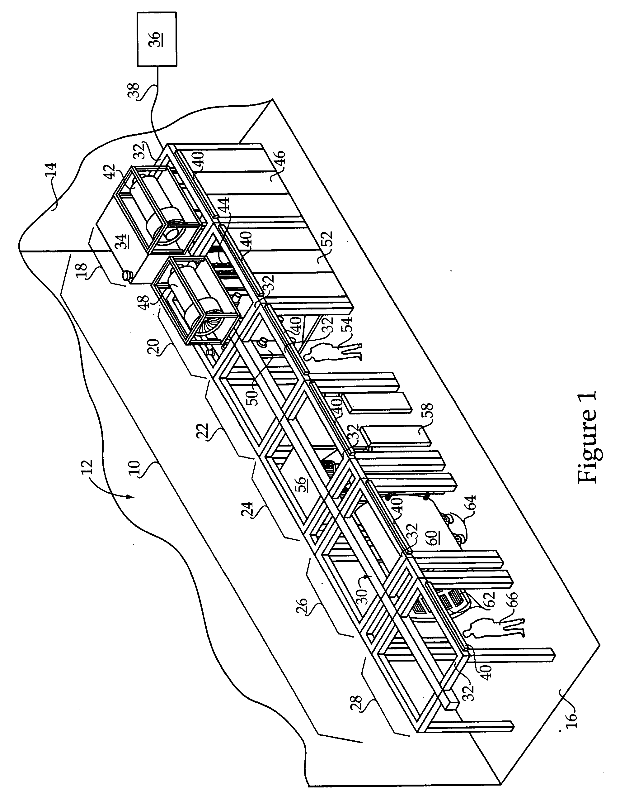
[0026]An exemplary embodiment of a manufacturing chain 10 is shown generally in FIG. 1. The manufacturing chain 10 may be disposed within a manufacturing area 12, such as, for example, a manufacturing area defined by a building 14. According to one embodiment, the manufacturing chain 10 may be secured to, and positioned above, a planar floor 16 of the manufacturing area 12. However, numerous locations and arrangements are contemplated for the manufacturing chain 10. According to the exemplary embodiment, the manufacturing chain 10 may be used to perform a paint process, such as, for example, a powder coating process, and, therefore, may also be referred to as a paint line. Although a paint process is described, however, it should be appreciated that the manufacturing chain 10 may be designed to perform any of a variety of manufacturing processes.

[0027]The manufacturing chain 10, also referred to as a modular manufacturing chain, may include several modular manufacturing stations, su...


PUM

PropertyMeasurementUnit
Lengthaaaaaaaaaa
Weightaaaaaaaaaa
Angleaaaaaaaaaa

Abstract

A material handling system includes a composite beam including an upper rail and a lower track connected through a plurality of spaced apart transverse members. A trolley includes an upper set of wheels and a lower set of wheels. The lower set of wheels is received within two parallel channels defined by the lower track. A drive tube is positioned between the upper rail and the lower track such that the upper set of wheels are in frictional engagement with the drive tube. A drive system is configured to rotate the drive tube.

Description

CROSS-REFERENCE TO RELATED APPLICATIONS[0001]This patent application is a continuation-in-part of U.S. patent application Ser. No. 12 / 151,881, filed May 9, 2008.TECHNICAL FIELD[0002]The present disclosure relates generally to a material handling system, and more particularly to a friction drive material handling system including a composite beam.BACKGROUND[0003]During a manufacturing process, a product is typically advanced through a plurality of manufacturing stations of a manufacturing chain. Specifically, the product is transported through each of the manufacturing stations along an article transportation device. At each manufacturing station, a specific one of a plurality of tasks in the manufacturing process is performed. All equipment and other components necessary to perform the assigned task are positioned, and often permanently affixed, at each manufacturing station. As a result, and dependent upon the number of tasks and the complexity of the manufacturing process, a manuf...

Claims


Application Information

Patent Timeline
IPC IPC(8): B66C1/10
CPCB05B13/0264B05B15/1207Y10T29/49716Y10S118/07B65G43/10B05B16/20
Inventor SPANGLER, JOHN M.BILSON, DAVID G.
Owner CATERPILLAR INC
Why Eureka
Try Eureka