
High-order harmonic rejection mixer using current steering technique

a current steering and mixer technology, applied in the field of mixers, can solve problems such as significant power efficiency reduction

Inactive Publication Date: 2009-11-12
SAMSUNG ELECTRO MECHANICS CO LTD
View PDF7 Cites 24 Cited by
  • Summary
  • Abstract
  • Description
  • Claims
  • Application Information

AI Technical Summary

Benefits of technology

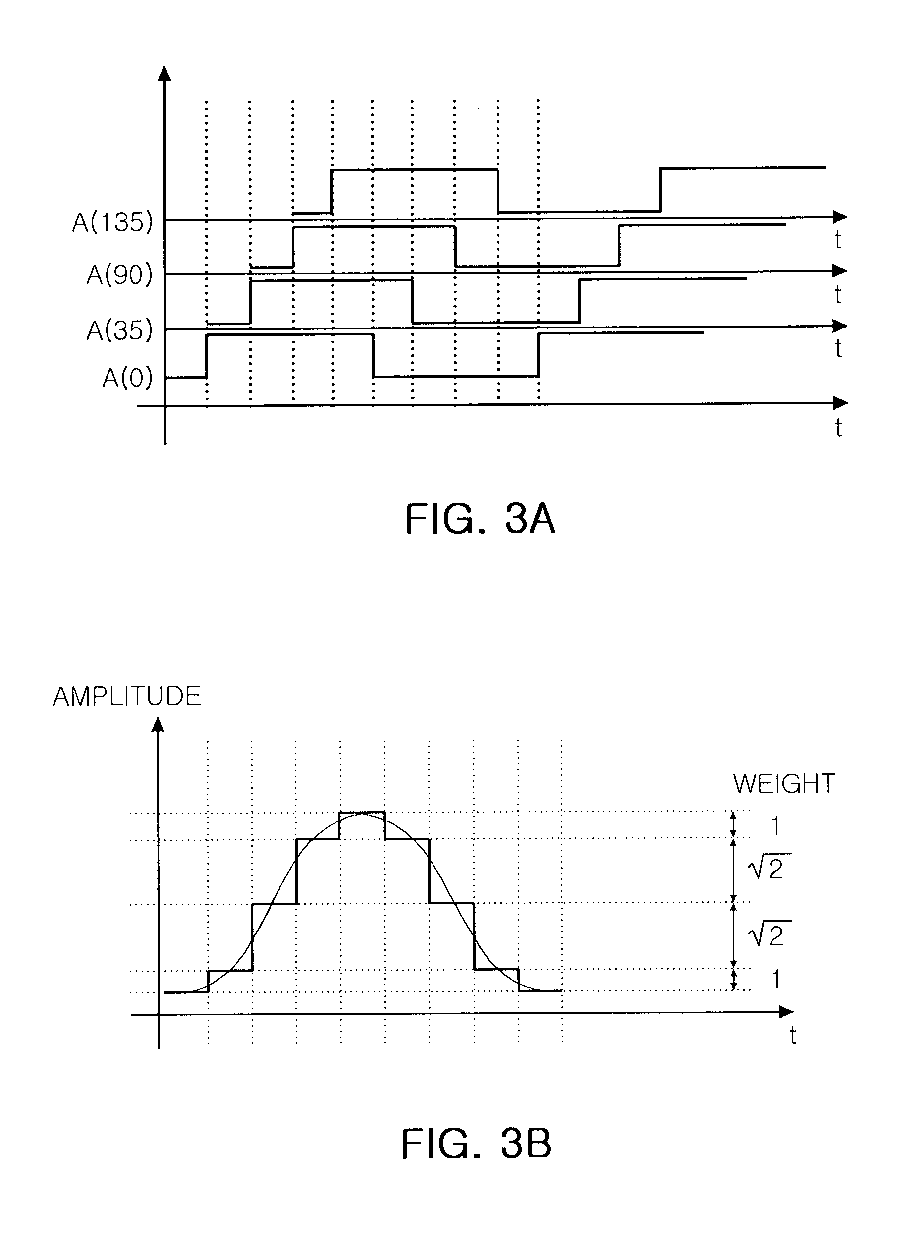
The present invention provides a high-order harmonic rejection mixer that uses a current steering technique to receive an input signal and generate an output signal. The mixer includes input current generation, transistors, and a load unit. The transistors are connected in a way that allows for the input of local oscillator signals with different phases, which are then used to generate an output signal. The transistors are designed to have a current that follows a sinusoidal waveform. The technical effect of this invention is to improve the performance of mixers by reducing harmonic distortion and improving signal-to-noise ratios.

Problems solved by technology

Further, the mixer circuits, which are individually provided at the phases of the LO signals, each include a circuit used to convert an input signal into a current, which causes a significant reduction in power efficiency.

Method used


Image

  • High-order harmonic rejection mixer using current steering technique
  • High-order harmonic rejection mixer using current steering technique
  • High-order harmonic rejection mixer using current steering technique

Examples


Embodiment Construction

[0019]Exemplary embodiments of the present invention will now be described in detail with reference to the accompanying drawings. The invention may however be embodied in many different forms and should not be construed as limited to the embodiments set forth herein. Rather, these embodiments are provided so that this disclosure will be thorough and complete, and will fully convey the scope of the invention to those skilled in the art. In the drawings, the shapes and dimensions may be exaggerated for clarity, and the same reference numerals will be used throughout to designate the same or like components.

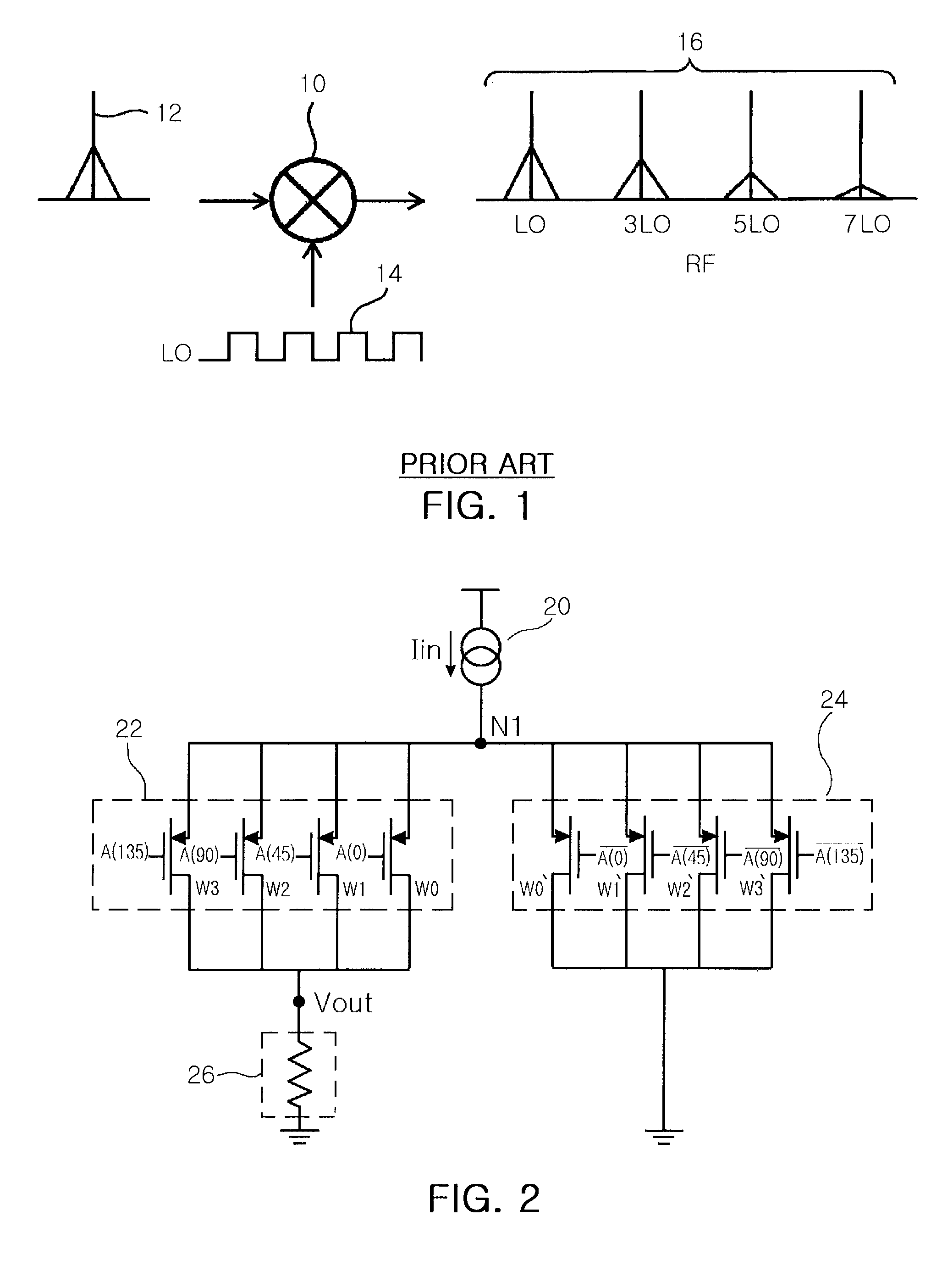
[0020]FIG. 2 is a circuit diagram illustrating a mixer using a current steering technique according to an exemplary embodiment of the invention.

[0021]Referring to FIG. 2, an input signal that will be subjected to frequency conversion is converted into a current by an input current generation unit 20. The current that is converted and output by the input current generation unit 20 is...


PUM


Abstract

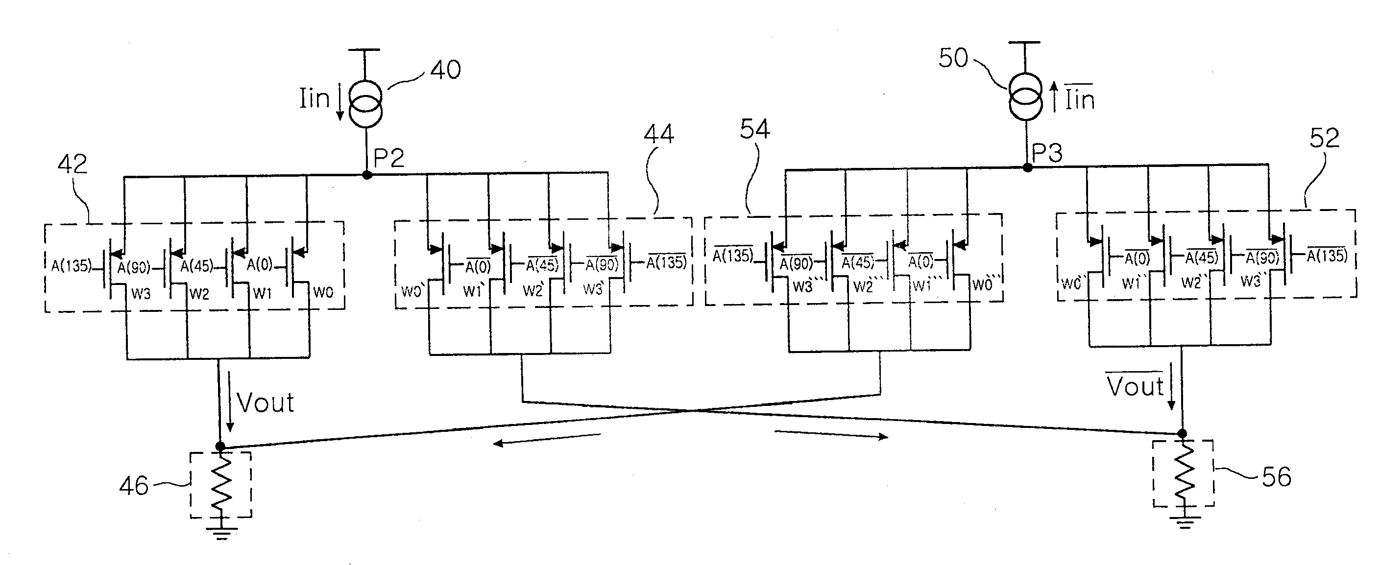
A mixer includes, an input current generation unit generating an input current; a first path circuit unit including n number of transistors having sources connected in common to an output node of the input current generation unit; and a second path circuit unit including n number of transistors having sources connected in common to the output node of the input current generation unit, and respectively corresponding to the n number of transistors included in the first path circuit unit. Local oscillator signals sequentially phase-shifted by 180° / n are individually input to gates of the n number of transistors included in the first path circuit unit, and local oscillator signals having opposite phases to the local oscillator signals input to the gates of the corresponding transistors included in the first path circuit unit are individually input to gates of the n number of transistors included in the second path circuit unit.

Description

CROSS-REFERENCE TO RELATED APPLICATIONS[0001]This application claims the priority of Korean Patent Application No. 2008-0043637 filed on May 9, 2008, in the Korean Intellectual Property Office, the disclosure of which is incorporated herein by reference.BACKGROUND OF THE INVENTION[0002]1. Field of the Invention[0003]The present invention relates to mixers, and more particularly, to a high-order harmonic rejection filter using a current steering technique that can generate a sinusoidal wave oscillator signal from a plurality of square wave oscillator signals having different phases from each other.[0004]2. Description of the Related Art[0005]In general, a mixer is a circuit that functions as a multiplier of two input signals. A mixer is used to down-convert a radio frequency (RF) signal having high frequency to an intermediate frequency (IF) signal having low frequency or a baseband signal. The mixer is also used to up-convert the IF signal or the baseband signal to an RF signal.[000...

Claims


Application Information

Patent Timeline
Patent Type & Authority Applications(United States)
IPC IPC(8): H04B1/16
CPCH03D7/1441H03D2200/0043H03D7/1483H03D2200/0086H03D7/00H03D7/18
Inventor PARK, KYOUNG SEOKKIM, NAM HEUNGCHOI, JEONG KIMOON, YO SUBKIM, GYU SUCKSEO, SEUNG WONKIM, YOO HWAN
Owner SAMSUNG ELECTRO MECHANICS CO LTD
Learn More